Smart Feature Command

For Smart Feature - Draw Features Documentation - Click Here
Command Licensing and Default Menu Location
- The Smart Feature Command is licensed to the RPS Smart Suite Command library
- The Smart Feature Command is located on the RPS Smart Suite Menu
- The Smart Feature Command is placed in the Takeoff menu ribbon group
Command Description
A new Feature Library driven approach to Data Prep and Takeoff workflows. Features can be drawn, assigned, created from survey data, created by tracking existing linework, tracking regions between existing linework or by shrink wrapping linework.
Smart Features know whether they are open lines, closed lines or point based.
Smart Features carry the material assignments required for Topsoil Sripping, Demolition, Subgrade Adjustment, and Topsoil Respread so that they are 100% ready for Takeoff.
Smart Features carry dynamically linked attributes that display the material quantities in the properties pane, and that update with changes to the length or area of the feature itself, or to the material thicknesses assigned to the materials.
Smart Features know what Layer, Color, Linestyle, and Name that they should have, and also what type of Elevation sould be assigned to them (2D, 3D Single, 3D Variable).
Smart Features also know whether they should report Earthworks Sub Quantities in the final Takeoff Report.
Smart Features can include additional information including Concrete Reinforcement i.e. Rebar, Tiebars and Dowel Baskets / Dowel Rods based on formulaic calculations for Length Width Features.
Smart Features include
- Generic Point Features e.g. Spot Elevations that have no material quantity
- Generic Line Features e.g. Existing or Proposed Contours that have no material quantity
- Generic Area Features e.g. Grading Limits or Phase / MOT Areas that have no material quantity
- Count Features e.g. Road Signs, Tees, bends that generate count quantities for Takeoff
- Length Features e.g. Curb, Fence. Wall that generate length quantities for Takeoff
- Area Features e.g. Topsoil Strip, Landscaping, Building Pad that generate area / volume quantities for Takeoff
- Length Area Features e.g. Curb with or without subgrade slab materials that generate length / volume quantities for Takeoff
- Length Width Features e.g. Road Pavement Lanes that generate area / volume quantities for Takeoff that can also include supplemental quantities e.g. for Concrete Reinforcement Materials based on formulaic association with the determined length and width of the feature.
- Pipe or Cable Features that generate Utility Pipe or Cable quantities for Takeoff
- Structure Features e.g. Catch Basins, Drainage Inlets, manholes that generate Utility Structure quantities for Takeoff
- Fittings e.g. Tees, Bends, Stops, Meters, Valves and Hydrants that generate Utility Fitting quantities for Takeoff.
Smart Features report directly into the integrated Spreadsheet Report that is dynamically linked to the Smart Feature, so that the report updates directly with changes to the Smart Feature itself.
Featurization is a process through which imported CAD, imported Survey data, or extracted PDF data is converted into constructible features like building pads, road pavement, sidewalk, parking areas, curb lines etc. which sets up naming, colors, layers, linestyles, incorporates materials, quantities and pay item information.
Release History
Dec 2025
Version 1 of Smart Feature released with v2026.1 of the RPS Command Library
Video Demostration
The following video provides an overview of the Smart feaure command
Coming soon
The following video shows how to utilize the Smart Feature command
Coming Soon
The following video shows how to use the Smart Feature command to carry out a 2D Concrete Takeoff for Sidewalk Areas and Curb Lines
Managing Your Smart Feature Library
When you run the Smart Feature command for the first time in any new TBC Project, you will be asked to select a Smart Feature Library. The Smart Feature Library files are stored in your RPS Settings folder in a subfolder called \RPS Smart Feature Libraries\. The files will have a .rps file extension.
The Smart Feature Library that you select will be copied into the current project’s project Folder, and will be renamed to match the name of the TBC Project. A copy of the project’s Smart Feature Library will be made in the RPS Settings folder (as described above), and will be maintained as you update the open project’s Smart Feature Library.
In this way, as you make changes or additions to the current project’s library, a copy of that library will be available in your RPS Settings folder for any future project that you may wish to start.
In this way, every TBC Project has a unique and stand alone Project Library, but you will be developing and evolving a centralized master that you can use for future project’s.
You will need to maintain your RPS Settings folder over time, and archive the settings files that you no longer need. Eventually, you will find that your Master File is no longer changing much from project to project.
Remember however that an addition you make to one project, will not automatically be in any other project’s Smart Feature Library unless it is a new project and you utilized the latest update to that project’s library to start the new project.
Selecting The Feature Library For a TBC Project
When you start out, we recommend that you take a look through the default RPS Feature Library to get a feel for how to organize your Features.
- Start a New TBC Project
- Run Smart Feature Command from the Smart Suite Menu or Modeling Menu of RPS Navigator Puck Menu.
- You will be prompted to Select file as follows
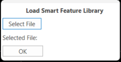
Click the Select File button, select the file named RPSSmartFeature.rps to open the RPS default library. Once selected, click OK to continue with the RPS Smart Feature command.
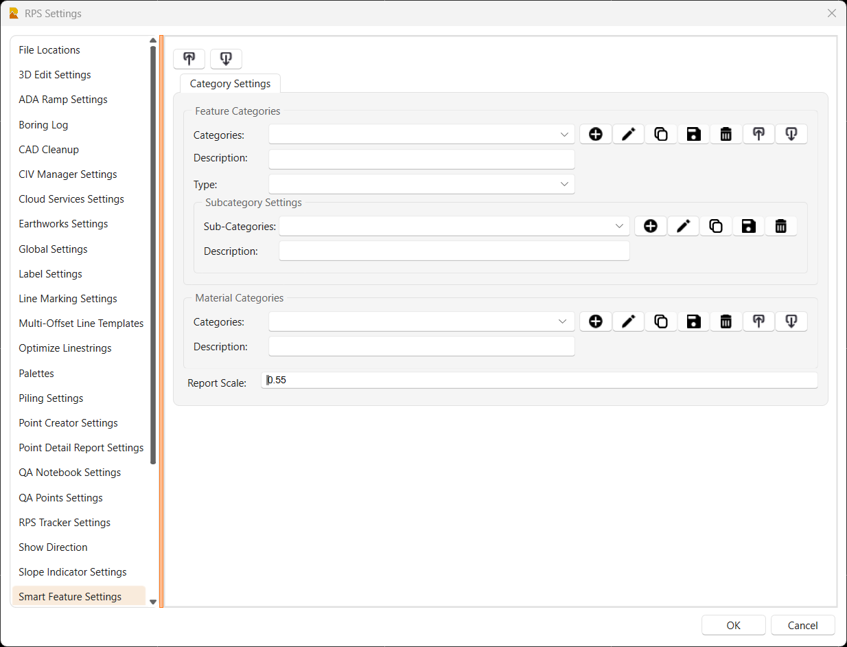
RPS Settings - Smart Feature Settings
Feature Categories and Feature Sub Categories
Most of the controls for the RPS Smart Feature command will be found in the command itself, however the Feature Categories, Feature Sub Categories and Material Categories are defined using RPS Settings - Smart Feature Settings. These are defined centrally, and are then used by the Smart Feature Library files that you create on each project to manage and organize the library. You will find a number of Categories etc. are already defined for you, but you can add to those as needed to meet your speific requirements.
In developing the command, and establishing the right method to organize the Smart Feature Library, we found that this part of the process is the most important step tp work out. There are many ways that you could organize your features, the key to success is to not have too many or too few categories, and to avoid having categories with few features in them. These are some of the elements to consider.
Main Category Options for Smart Features could include any of the following
- Existing, Demolition, Proposed, Erosion Control, Site
- Plan, Cross Section, Profile Features
- Site Features vs Utility Features
- Generic Features (Contours, Spot Elevations, Phase Boundaries) that do not generate quantity information vs Features that do generate quantity information (Curb, Pavement, Rip Rap, Road Signs, Fire Hydrants etc.)
- Features defined by Areas (Polygons), Lengths (Lines), Counts (Points) or more advanced features defined by Length with Sectional Area (e.g. Curb with Subgrade) or Length with Width (e.g. Road Pavement Lanes).
- Types of Pavement i.e. Concrete vs Asphalt vs Gravel
We strongly recommend that you review the structure defined in the default RPS Smart Feature settings file, to see how that works, before starting to build your own Feature Library.
Select RPS settings from the header bar commands, and select the Smart Feature Settings. Here you can can Add, Edit, Copy, Save, Delete, Import and Export Feature Categories and Material Categories. You can also Add, Edit, Copy, Save and Delete Sub Categories. Note that we dont recommend that you delete Categories or Sub Categories unless you really have to, and certainly not once you have started work on the project. Remember that existing categories likely already have features within them, so deleting the category will also delete all of the features that exist within that category.
Feature Categories
The RPS Default Feature Library utilizes the following Feature Categories
- CADPR-Profile Feature - used for features created in Smart Profile e.g. Bridge Lines
- CADXS-Section Feature - used for features created on Cross Sections - (e.g. Phase 1 Fill)
- DEM-Feature - used for Demolition Features that are also Surface Features (e.g. Building Pad)
- DEM-Feature (ALC) - used for Demolition features that only drive a quantity (e.g. Stumps)
- EROS-Feature - Erosion Control Features
- EROS-Feature (ALC) (Silt Logs, Silt Fence etc.) that only drive a quantity
- EX-Feature - Existing Ground Surface Features that drive a suface and a quantity
- EX-Feature (ALC) - Existing Features that only drive a Non Demolition quantity
- EX-Generic - Existing Features that only form the Existing Ground Surface (e.g. Contours)
- FG-Feature - Finished Grade Features that drive a surface and a quantity
- FG-Feature (ALC) - Finshed Grade features that only drive a quantity (e.g. a Pavement Area)
- FG-Generic - Finished GradeFeatures that only drive a Surface (e.g. Contours, Spot Elevations)
- UT-Cable - Utility Cable Features
- UT-Fitting - Utility Fitting Features
- UT-Structure - Utility Strucrture Features
- UT-Pipe - Utility Pipe Features
- UTIL-Line Path - Plan View Lines that match Profile Drawing Lines in Smart Profile command
Note that the Categories are used to
- Organize your features in a logical structure
- Are used as filters to reduce pick lists in the Draw Features process
- Are used to organize feature quantities in the Takeoff reports
- Can be used to sort and filter grid view lists of features
- Can be used in searches when looking for a specific feature
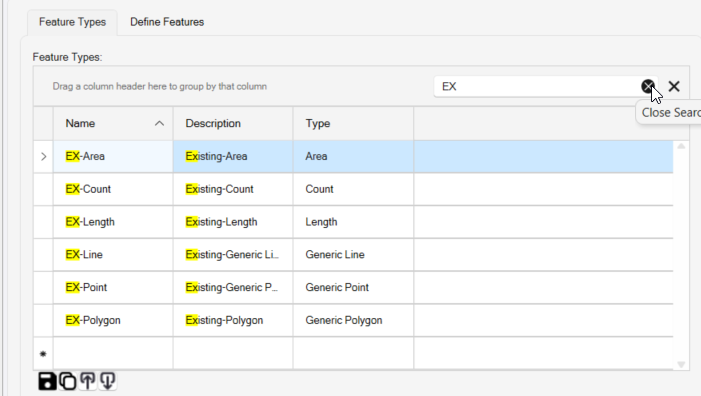
For example I could search by EX- to find all my Existing Features. I can Filter using EX-Feature to just show me a list of Features in that category etc. So naming your categories, sub categories and features in a consistent way will be important.
Each Feature Category has a Name, Description and is assigned to a Category Type (either Feature Categories or Utility Categories. When you assign the Category Type as Utility Category, those will be used in the Utility Feature workflows only.
Feature Sub Categories
Each Feature Category will have a number of Sub Categories which is used to further divide the list of features, again for logical structuring of your library and to make a long list of featurs easier to work with.
Note that the Sub Categories are used to
- Organize your features in a logical structure
- Are used as filters to reduce pick lists in the Draw Features process
- Are used to organize feature quantities in the Takeoff reports
- Can be used to sort and filter grid view lists of features
- Can be used in searches when looking for a specific feature
Each Sub Category has a Name and a Description. An Exampe list of Sub Categories that are beneath e.g. the FG-Feature Cattegory would be
- Area e.g. for HD Parking, LD Parking, Sidewalk, Building Pad
- Length e.g. For Curb or Striping or Fence Lengths
- Count e.g. for Road Signs or Wheel Stops
- Length Area e.g. for Curb & Gutter with Subgrade
- Length Width - e.g. for Road Pavement Lanes
You will find that in the RPS Feature Library method of organizing the Features, we use this approach for most of the Categories as we found that the most logical and easiest to work with structure, you may find that this does / does not work for you, depending on the specific featurs that you want to work with. The system is defined to give maximum flexibility so that you can structure your library the way that you want it.
Note that when we organize data in this way, you may feel that the Category / Sub Category and Feature Type definitions are somewhat a duplication - for this way of rganizing the data that is true, however, for other ways of organizing the data that would not necessarily be the same. The flexibility is there so that you can organize the data as you find most appropriate to your workload.
Material Categories
There are a number of pre defined material categories for you ti use, you can supplement these with addtional user defined categories as needed. The pre defined Material Categories are as follows
- Aggregates (Sand, Gravel, Crushd Stone, RipRap etc.)
- Composite Materials (Asphalt, Concrete etc.)
- Concrete Reinforcement (Rebar, Tiebar, Dowel Rods, Dowel Baskets etc.)
- Earthen (Native Topsoil, Soil, Weathered Rock, Rock etc.)
- Earthen Select (Any other select material that is not an Aggregate or other defined category)
- Geo-Synthetics (Geo-Textiles and Geo-Membranes etc.)
- Landscaping (Sod, Seed, Seed & Mulch etc.)
- Other Materials (Anything that does not fit an already defined Category)
- Sheet Piling
- Surface Treatments (Lime Stabiized Base, SubgradeCompaction, Tack Coat etc.)
- Utility Materials (materials used to build Utility Pipe, Cable and Structures i.e. Reinforced Concrete, PVC, HDPE, Steel, Ductile Iron, Corrugated metal, Vitrified Clay, Fiberglass reinforced Polymer, Precast Concrete etc.)
Report Scale
Note that the option Report Scale allows you to set how much of the Smart Feature command dialog height you will allow the report spreadsheet to fill. This is specific to the screen / monitor that you are using to run TBC, and the display settings that you are using for that screen in Windows. You can adjust this parameter to minimize scrolling of the dialog and to maximize the height of the report on screen.
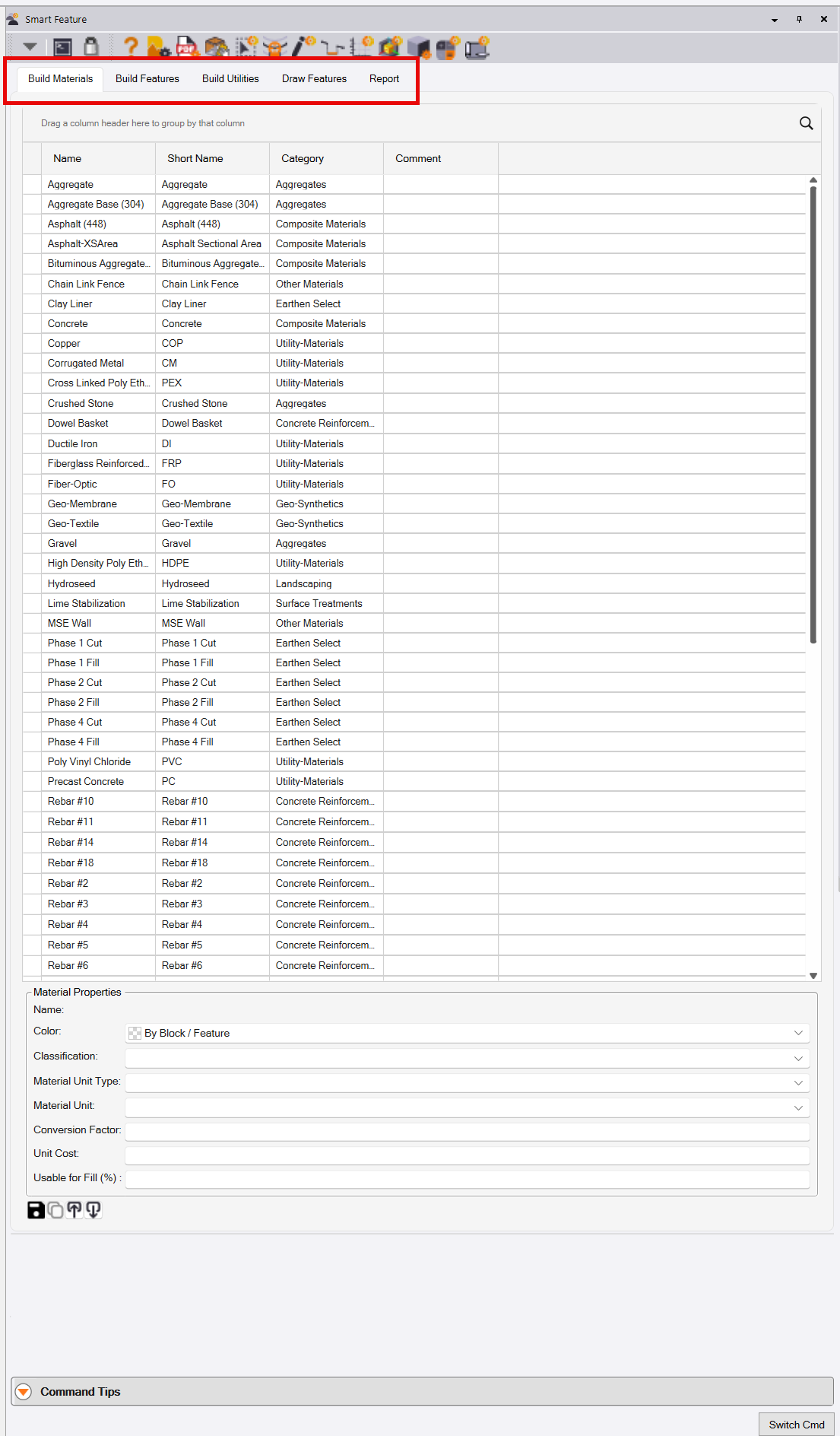
Smart Feature Command Structure
The Smart Feature Command is brioken into 4 process steps as follows
1 - RPS Settings - Smart Fearture Settings Process Steps
- Define Feature Categories
- Define Feature Sub Categories
- Define Material Categories
2 - Define Materials, Features and Utilities
- Define Materials
- Define Feature Types
- Define Features
- Define Utility Networks
- Define Utilities
3 - Create, Assign, Draw Features
- Draw Features
4 - Report Features
- Report
Once you have established your Materials and Features, you will predomninantly work in the Draw Features and Reports tabs of the command.
Build Materials
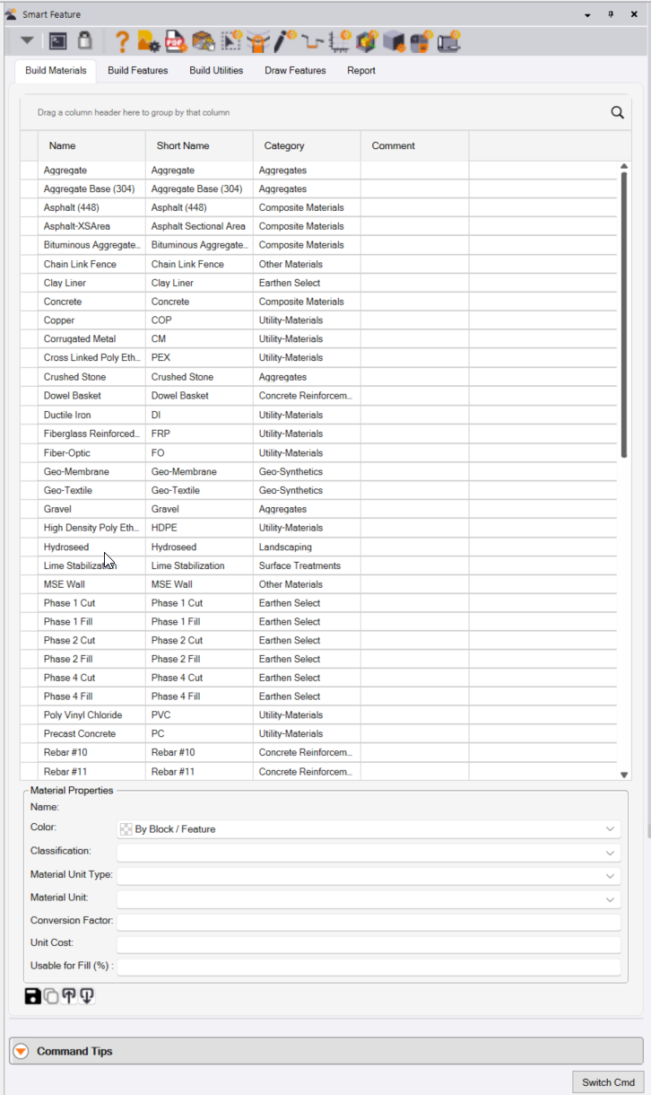
In this tab you will build your materials list for the project. The table of existing materials is displayed, and here you will find the
- Material Name
- Material Short Name
- Material Category
- Comments that may have been added to the material.
You can click in the column headers to sort the materials table alphabetically or reverse alphabetically based on the data values found in that column.
You can also select the Filter function in the column headers, and define a filter to reduce the number of materials presented in the table. The filter searches through the data values in the selected column and filters the list down to those that match the defined filter criteria. You can use the Search function to type in some characters to reduce the list of filter options to just those that match the characters entered. You can check the checkboxes by those elements that you want displayed in the table.
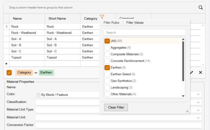
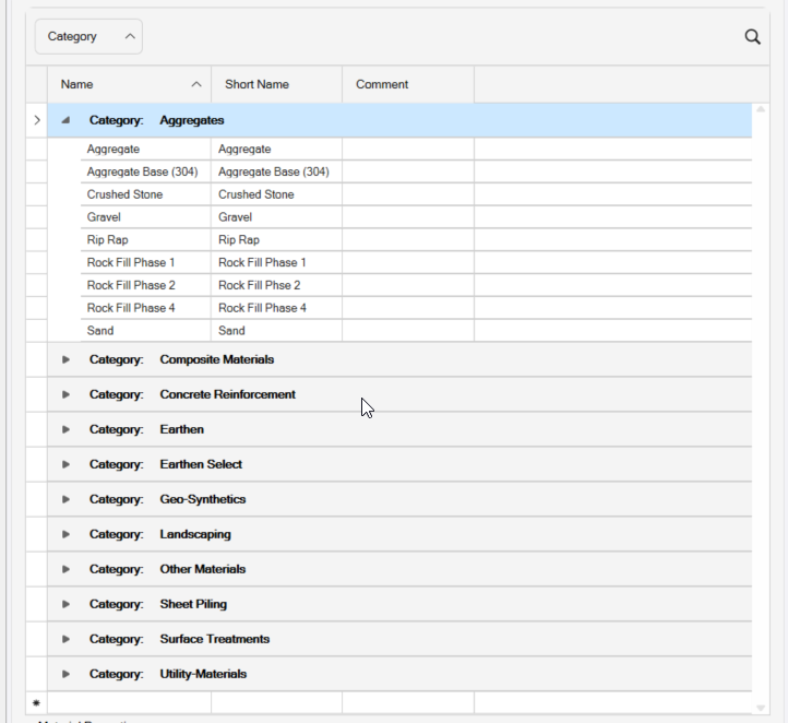
You can also select a column header and drag it into the area above the column headers to Group the data in the table by the data type in that columm e.g. the Category of Material.
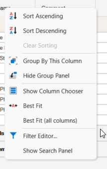
If you right click on the column headers, you will find these options available
If you right click on a row in the table you can select to Delete the row.
At the base of the table you will find the Materials Properties section, this displays more properties for the material highlighted in the table. For most material types, the Material Properties include
- Name
- Color
- Classification
- Material Unit Type (Length, Area, Volume, Count, Weight)
- Material Unit e.g. CY, LF, TON etc
- Conversion Factor i.e. if Unit is TON what is the CY to TON conversion factor
- Unit Cost (can be left blank if you are not using TBC for costing purposes)
There are some variations based on the Material selected.
For Earthen Materials the Material Properties include
- Name
- Color
- Classification (Stable Rock, Topsoil, Soil - Type A, Soil - Type B, Soil - Type C)
- Material Unit Type
- Material Unit
- Conversion Factor
- Unit Cost
- Usable for Fill (%)
- Cut Factor
- Fill Factor
- Haul Bulking Factor
Note that you should should apply either a Cut Factor or a Fill Factor (not both) if you want to compute volumes and apply Shrink or Swell factors to materials.
The Cut Factor is the shrinkage expected for the cut material when it gets placed as compacted fill e.g. 0.85 for a shrinkage of 15%. For example if we have 100cy Cut and 80cy Fill required, the cut would provide 85cy compacted fill i.e. a 5cy excess to requirement.
The Fill Factor is the expansion to apply to the fill required so that it can be balanced against native unshrunk cut e.g. 1.13 for a 13% bulking of the fill. For example if we have 100cy Cut and 80cy Fill required, the fill required would expand to 90.4 (loose fill) that would balance against 100cy loose cut and leave 9.6cy excess.
Haul Bulking Factor is the expansion of the cut material when it is in a loose haul state, and can be used to determine the number of truck loads needed to haul in material from offsite, haul material on site or to haul material away from the project. A value e.g. 1.20 would bloat 100cy of Cut up to 120cy of Loose Haul material.
You can leave the values that you do not want to apply to 1.0 and they will have no effect on the earthworks calculations for that material.
Material Units
Materials can be measured and reported in different measurement types and within those types in different measurement units. All measurements will be made as counts (Each) or Length (Linear Feet (LF)) or Area (Square Feet (SF)) or Volume (Cubic Yards (CY)) for example but you may need to report them in a different unit to the defaults or even a different measurement type e.g. Weight. So for example Asphalt may be measured by Area with a Depth of material to create a Volume, but it is measured in Tons so we need to have a conversion factor that defines how the Tons are computed from Cubic Yards.
Measurement Types and Measurement Units include
- Length - Linear Feet, Miles, Lane Miles (Meters, Kilometers, Lane Kilometers)
- Area - Square Yards, Square Feet, Acres (Square Meters, Hectares)
- Count - Each
- Weight - Tons, Pounds, Ounces (Tonnes, Kilograms, Grams)
- Volume - Cubic Yards, Cubic Foot, Gallons, Thouand Gallons (Cubic Meters, Litres, Megalitres)
All Materials can be assigned a Unit Cost if you want to calculate Material Costs in the reporting process.
Features and Utility Features
The RPS Smart Feature Library separates Features from Utility Features within the Smart Feature command.
Features
Features applies to all Features of the project including Building Pads, Road or Highways Pavement, Curb & Gutter, Sidewalk, Beauty Strip, Parking Areas etc. but excludes Utility Features that are handled separately (see below).
Utility Features
Utility Features applies to all utility features of the project including Pipes, Cables, Structures, and Fittings for all Utility Networks (Storm, Sanitary, Water, Electric, Cable, Gas etc.).
Feature Types and Features
Feature Types
Features have a Feature Type as well as a Category and Sub Category. The Feature Types define how the Feature will be measured in terms of a Takeoff.
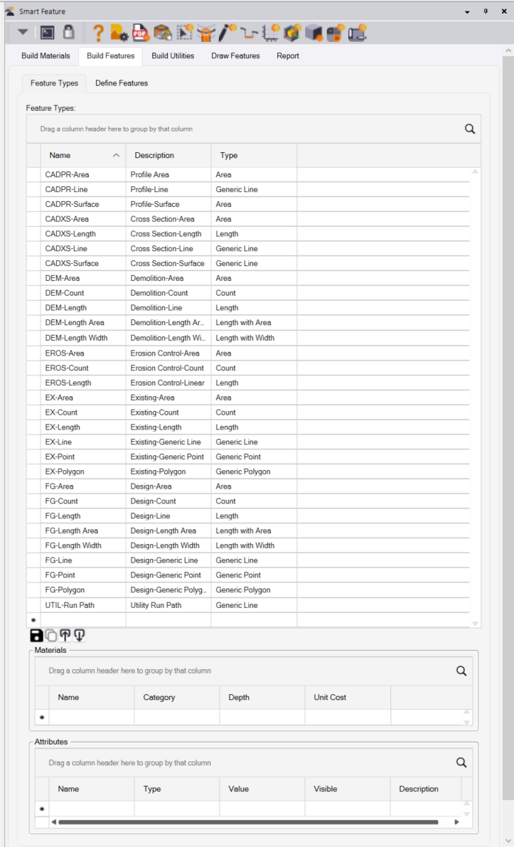
To define Feature Types and Features, select the Build Features tab of the Smart Feature command dialog and then select the Feature Types tab.
Generic Feature Types
Some Features (Generic Feature Type) do not generate a measurement for a Takeoff - for example Ditch Lines, Surface Breaklines, Contours, Spot Elevations, Project Boundaries, Phase Boundaries, Grading Limits etc. Generic Feature Types are defined as follows
- Generic Polygon e.g. Site Boundary or Grading Limits
- Generic Line e.g. Existing Contours or Surface Breakline
- Generic Point e.g. Spot Elevations
Standard Feature Types
Other Features do generate quantity measurement(s) for a Takeoff - for example Building Pad Areas, Topsoil Strip Areas, Demolition Areas, Road Pavement Lane Areas, Parking Lot Areas, Sidewalk Areas, Curb Lengths, Sign Counts, Striping Lengths etc. These Feature Types are defined as follows
- Area - e.g. Building Pad, Parking Lot Area, Sidewalk Area
- Length - e.g. Curb Line Length, Striping Length, Fence Length
- Count - e.g. Sign Count, Tree Count, Bush Count, Wheel Stop Count
- Length With Area - e.g. Curb Line length with Sectional Area for Curb and Subgrade
- Length With Width - e.g. a 12’ wide Road Pavement Lane
Creating a Feature Type
You can create as many Feature Types as you need, each Feature Type that you create will have one of the above Type assignments. Every Feature that you create later will be assigned a Feature Type from those that you define here.
We recommend that you elect a consistent naming convention for Feature Types and Features, here are some example Feature Type names that we defined
CADPR-Area = Profile Drawing Areas (Area)
CADPR-Line = Profile Drawing Lines (Generic Line)
CADPR-Surface = Profile Surface Lines (Generic Line)
CADXS-Area = Cross Section Drawing Area (Area)
CADXS-Length = Cross Section Lengths (Length)
CADXS-Line = Cross Section Line (Generic Line)
CADXS-Surface = Cross Section Surface (Generic Line)
DEM-Area = Demolition Area (Area)
DEM-Length = Demolition Length (Length)
DEM-Count = Demolition Count (Count)
FG-Area = Finished Grade Area (Area)
FG-Length = Finished Grade Length (Length)
FG-Count = Finished Grade Count (Count)
FG-Line = Finished Grade Line (Generic Line)
FG-Polygon = Finished Grade Polygon (Generic Polygon)
FG-Point = Finished Grade Point (Generic Point)
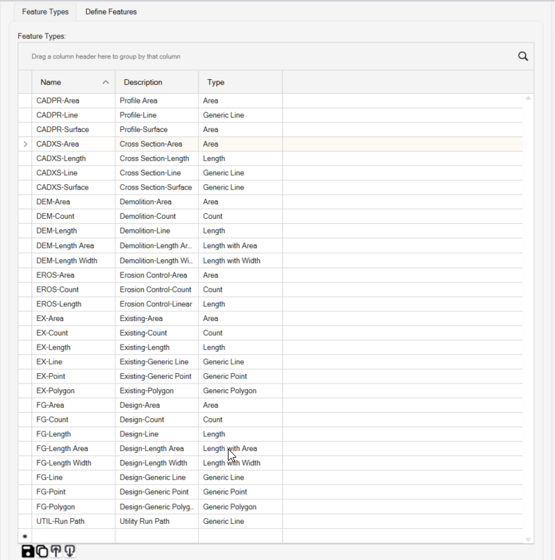
To create a new Feature Type, simply go to the bottom of the list of Feature Types displayed (as above) and enter the new Feature Type into the blank cells at the bottom of the list. Use the Tab key to move between fields. Once the basic feature Type is defined, you can then add materials and Attributes as necessary in the section below the list.
The buttons at the base of the list table allow you to Save a Feature Type, Create a Copy of the currently selected Feature Type, to Import or Export your feature Types To / From an Excel spreadsheet.
Note that the Feature Types list table can be manipulated as follows
Sort the Table
Click in any column header of any column to sort alphabetically or reverse alphabetically
Filter the Table
Click the Filter button in the column header of any column and yu can search or apply a filter to the Table based on the data types in that column of the table
Group the Table
Drag the column header of any column into the area above the column headers in the table to group the data in the table based on the data values in the column header that you selected.
Right Click in the Column Header
This reveals a right click menu of options that you can use to manage the data in the table
Right Click a Date Row in the Table
This allows you to elete a row in the table.
Search
Click the Search button in the top right corner of the data table yto opn the Search function. Enter a character string in the Search field and the data in the table will be reduced to just rows of data that match the Search criteria in play.
Each Feature Type has a Name, a Description and a Type. You can also assign Default Materials and Default Attributes to any Feature Type that will be automaticaly created on any Feature that is given that Feature Type. For example CADXS features may want a Station and a Phase Attribute so that you can sort the features defined at each Cross Section Station by Station and or Phase when you get round to reporting in your Takeoff process.
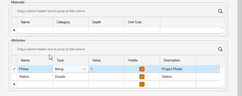
Materials
The Materials section allows you to define default Materials for this specific Feature Type. Note that it is more common to define the Materials at the specific Feature level of the library, however if you have a group of Features that all have the same type and the same material structure then you can create a feature Type and assign the type to have default materials.
The Material Name is selected from a pull down list of all the Materials that you have defined in your feature Library (see the Materials Definition section of this document).
When you select a Material, its Material Category will be automaticaly selected.
You can assign a default Depth e.g. 10” for the Material Layer
The Unit Cost will be auto populated based on the Unit Cost value assigned to the Material that you selected (see the Materials Definition section of this document).
Attributes
Attributes can have a name e.g. Station, a Type that you select from a list of Types including
- String = a character string e.g. ABC123
- Integer = a numerical value that is Integer only e.g. 12
- Double = a numerical value that has decimal places e.g. 123.12
- List = a list of options that you want to chosse from e.g. Class I, Class II, Class III
You can input a default value for the attribute, the default can be overridden when you create the feature as needed.
The Attribute Visibility column controls whether the Attribute will be displayed in the Properties Pane for the feature when it is selected graphically, and whether the attribute will be displayed in the Takeoff Reports (will display in properties and will create a column of values in the Takeoff report if set to checked On).
The Attributes can also be given a description as needed
Define Features
The Define Features function allows you to define all of the features that you will need for your projects. Features are organizd by Category and Sub Category as defined earler in the process using the RPS Settings - Smart Feature Settings functions.
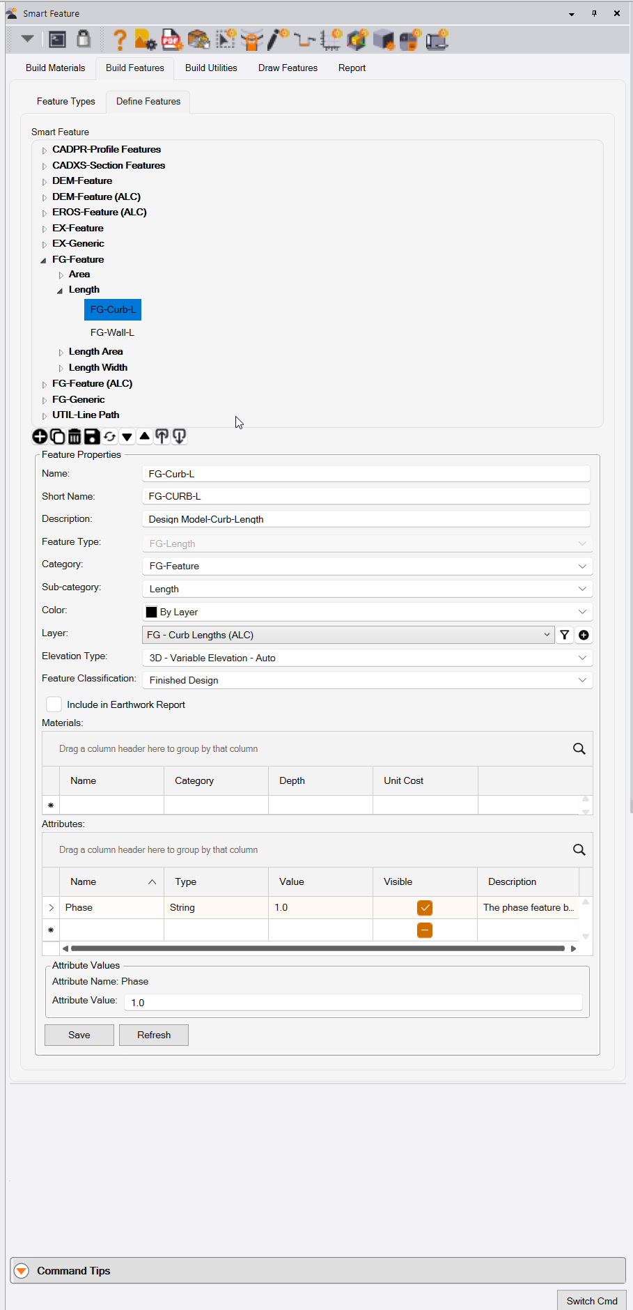
In the top section of the Define Features tab, you can see the Features that have alreay been defined. The Categories and Sub Categories can be expanded to reveal the Features.
Click on a Feature to reveal the Feature Properties, Materials and Attributes that have been defined for the feature selected in the lower section of the dialog.
The buttons below the Feature list allow you to
- Add a Feature
- Copy a Feature
- Delete a Feature
- Save a Feature
- Refresh the Features List
- Expand all of the Feature Categories and Sub Categories
- Collapse all of the Feature Categories and Sub Categories
- Import or Export the feature definitions to / from an Excel Spreadsheet
Feature Definitions
All Features have the following Feature Properties
- Name
- Short Name
- Description
- Feature Type (See Feature Types for more details)
- Category (See Feature Categories for more details)
- Sub Category (See feature Sub Categories for more details)
- Color (Typically set to By Layer or if needed select a specific color)
- Layer (Select the Layer on which these Features will be placed or drawn)
- Elevation Type (Features can be drawn as 2D, 3D Single Elevation (Pads or Contours), 3D Variable Elevation (manual) or 3D Variable Elevation (Auto) (Curbs, Sidewalks etc.), or 3D From Surface. This selection dictats how a feature will be elevated as it is assigned or drawn / created. You can select a 3D option here and still override it to e.g. 2D when you create the Feature in the Draw features process.
- Feature Classification - this allows you to assign a classification to the Feature that is used in the Smart Takeoff process to determine which Features can be used to apply Subgrade Adjustments to. The options here include Existing, Finished Design, Erosion Control, Temporary Works, Other.
- Include in Earthwork Report checkbox - when checked, this feature will create an earthworks report line item in the Takeoff Reports, that defines the Cut, Fill and Balance sub quantities that lie beneath this Feature and all instances of this Feature will be reported this way.
Short Name and Auto Processing of Imported Survey Data
Note that the Short Name can be used to autoprocess imported survey data. If the features of the survey are coded using the Short Name, then in the Draw Features process, you can select all of the Survey Features and auto process them into RPS Smart Features in a single step. The Smart Features wil then have the Material quantities and Attributes associated with them in the properties pane, will be automatically added to the Smart Feature and the Smart Takeoff Reports, the Features will also be on your preferred layers and will be assigned the colors and fill colors associated with the feture Definitions.
Feature Materials
All Features can be assgned Materials
In the Materials area of the dialog, you can select one or more materials to be applied to a feature as it is created. The materials are primarily used for features that have a plainmetric area or a cross sectional area i.e. Features that have Feature Type Area, Length with Area, or Length with Width, however you can also use Materials for e.g. Length Features e.g. Striping Materials, fence materials, Guard Rail Materials etc. or for Count Features e.g. Sign Posts can have a Pole and a sign and a concrete Foundation Material. If you carry out landscaping operations, Tree features could have a material Large Tree, Small Tree etc, or a Coniferous Tree or Deciduous Tree for example.
Select the Material Name from the list of materials
The Material Category will be autofilled based on your Material Library configuration
Enter the depth of the material in Inches or mm
The Unit Cost will be autofilled based on your Material Library configuration
For example a Building Pad may have 10” of Concrete on top of 6” of Aggregate material.
When you are defining Length with Area features e.g,. for a curb and subgrade feature such as that shown below
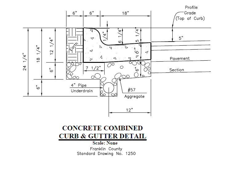
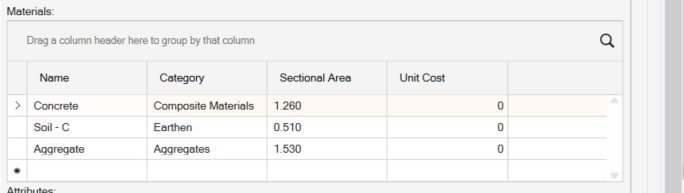
The Materials for a Length Area Feature would look as follows, where each of the 3 areas of the feature (the curb, the subgrade, the earth backfill) are listed with a material and a material secrional area. (The areas can be determined in TBC if you import and georeference the curb detail and then you can trace off the areas using theTBC CAD functions).
The Materials for Length with Width Features can be used to define e.g. Road Pavement Lanes. If the Road Pavement is either Jointed or Continuous Concrete Pavement, the Materials definition for these types of Feature can also include concrete reinforcement parameters so that the quantity of Rebar, Tiebars and Dowel Baskets can also be determined. The Materals would look as follows for these types of Feature
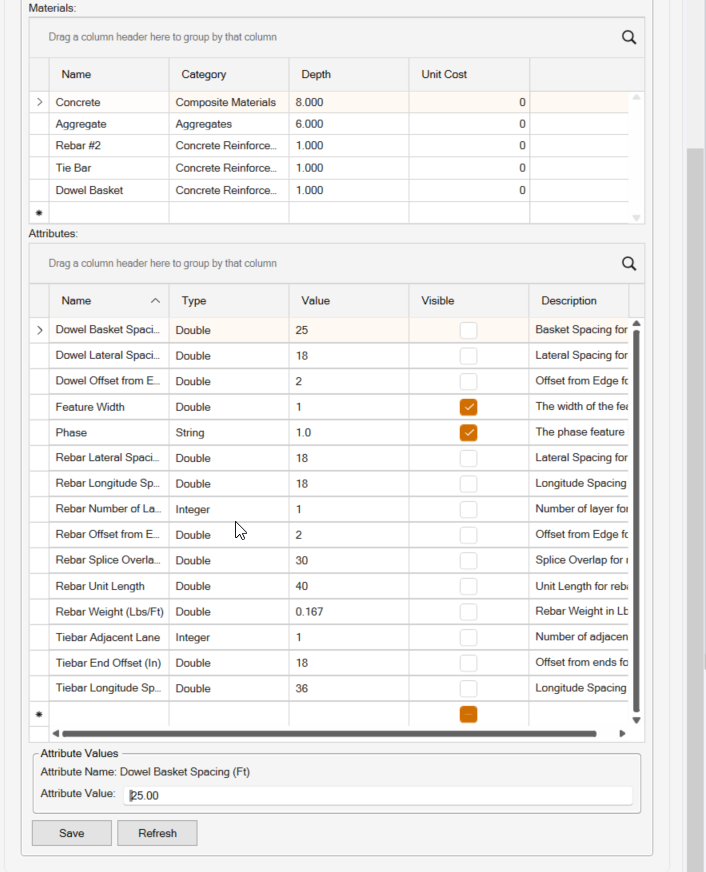
In the Materials section you would enter Materials like Rebar, Tie Bar and Dowel Basket, and in the Attributes Section which is then auto populated with all of the parameters required to compute the quantites of these materals based on the length and width of the defined pavement lane.
Rebar Calculations
The rebar calculations use the following inputs
- Rebar Lateral Spacing
- Rebar Longitudinal Spacing
- Rebar Number of Layers
- Rebar Offset from Edge (In)
- Rebar Splice Overlap
- Rebar Unit Length
- Rebar Weight (lbs / linear Foot)
The length of the Feature is then divided by the longitudinal spacing and the edge offset is applied to the start and end of the lane and the left and right side of the lane to determine the number and length of the lateral bars required.
The width of the Feature is then divided by the lateral spacing and the edge offset is applied to the left and right side of the lane an\d the start and end of the lane to determine the number and length of the longitudinal bars. The splice overlap and rebar unit length is then used to adjust the total longitudinal length required for the rebar.
The total number and length of lateral and longitudinal bars is then multiplied by the number of layers and the lbs / linear foot value to determine the toal lengh and weight of the rebar required for that pavement lane feature.
The report and properties pane will show the rebar quantities to build the Feature.
Note that the length width feature has to remain a length width feature for these values to be computed correctly. e.g. a Grip Edit to the object is currently not supported, at some point we will provide a dedicated editing tool for the object so that you can change its width or modify its start or end staion and have the quantities update dynamically.
Tie Bar Calculations
Tie Bars are used to link adjacent pavement lanes together. The Tie Bar calcuations will request the following additional inputs
- Tie Bar Adjacent Lane (input 0, 1 or 2) - this value defines if there is an adjacent lane on either, both or no sides of the pavement lane defined by the lengt Width feature. If the entered value is 0 ten no Tie Bars are required. If the entered value is 1 or 2 then Tiebars are required on either 1 or 2 sides of the pavement lane.
- Tie Bar End Offset - this is the offset in inches of the first and last Tiebar along the side of the Pavement Lane
- Tie Bar Longitudinal Spacing (In) - this is the longitudinal spacing between the Tie Bars along the side of the Pavement Lane.
The length of the Feature is used, along with 2x the End Offset and the Longitudinal spacing to determine the number of Tie Bars required.
The report and properties pane will show the number of Tie Bars required to build the Feature.
Dowel Basket Calculations
For jointed pavement, dowel baskets containing dowel rods are placed at equally spaced locations along the pavemet lane. The Dowel Rods create a strengthening between the jointed sections of pavement. The Dowel Basket calcuations will request the following additional inputs
- Dowel Basket Spacing (Ft) - this is the longitudinal sacing between the Dowel Baskets
- Dowel Lateral Spacing (In) - this is the spacing of the Dowel Rods in the Dowel Basket
- Dowel Offset from Edge (In) - this is the offset of the first and last dowel rod from the edge of the Pavement Lane Feature.
The number of dowel baskets is computed using the Length of the Feature divided by the Dowel Basket Spacing.
The Number of Dowel Rods in the Dowel Basket is computed using the Width of the Feature and 2x the Edge offset and the Lateral Spacing between the Dowel Rods.
The report and properties pane will show the number of Dowel Baskets and the number of Dowel Rods required to build the Feature.
Feature Attributes
In addition to the above “specialist attributes” other attribues can also be added to Features. Examples could include any of the following
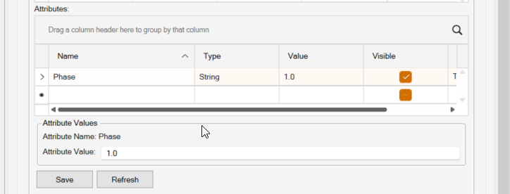
- Phase - so that you can assign a Project Phase to any / all Features that can be then usd to Group Fetures in the final reports
- Station - when working with Cross Sections, if you trace off areas in the Cross Sections as Features, you can assign a Station to all of the Features created from the same Cross Section so that you can use the reported areas for End Section Area Volume Calculations in the Excel reports.
If you want to capture additional details for a fewture, you can use the Attributes to do that e.g. you may want to note which Quarry will be sed to source a material, or which supplier you will be using etc.
Utiity Networks and Utility Features
To start the Utility Feature definition process, select the Bulid Utilties tab in the dialog.
The Utility process defines Utility Networks and Utility Features.
Utility Network
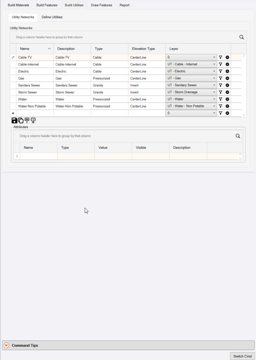
To review or create a Utility network click the Utility Networks tab.
Utiity Networks include the following
- Storm Sewer
- Sanitary Sewer
- Water
- Water - Non Potable
- Gas
- Electric
- Cable TV
- Cable - Internet.
The buttons at the base of the list of networks alow you to Save, Copy a Network, Import or Export your Utility Networks To / From an Excel Spreadsheet.
To create a new Utility Network, click in the bank cells at the base of the list of Utility Networks. Use the Tab key to move between cells in the grid.
The Utiity Network defines the following key elements for a Utility Feature that is created within the Utility Network.
- The Name of the Utility Network
- A Description for the Utility Network
- The Type of Utility Network - options include Gravity, Pressurized, Cable, User Defined
- How the linear utility features (Pipe, Cable, Conduit etc.) will have their elevaions defined i.e. Invert, Centerline, Crown, Soffit, Bottom, Bell, etc. Typically you will choose Invert for most Utiity Networks, but for some like Gas or Water you may choose Centerline for example.
- Which Layer the features of the network will be placed on as they are created. You can click the + key beside the Layer selector to create a new layer if needed.
In addition you an define additional user defined attributes that you may want to assign to Utility Features that you create within this Utility Network
- Attributes could include e.g. Project Phase i.e. if as you build out the Storm Network elements, you know that these Pipes and Structures belong in Phase 1, and these belong in Phase 2, you can create a project phase Attribute and assignb the Phase to the features as they are being assigned or created.
Note that Attributes that you define here will apply to every Feature that you create in this Utility Network. You can also create Attributes at the specific Feature level also which will only apply to that speciic feature type.
Utility Features
To define Utility Features click the Define Utilities Tab of the Build Utilities dialog.
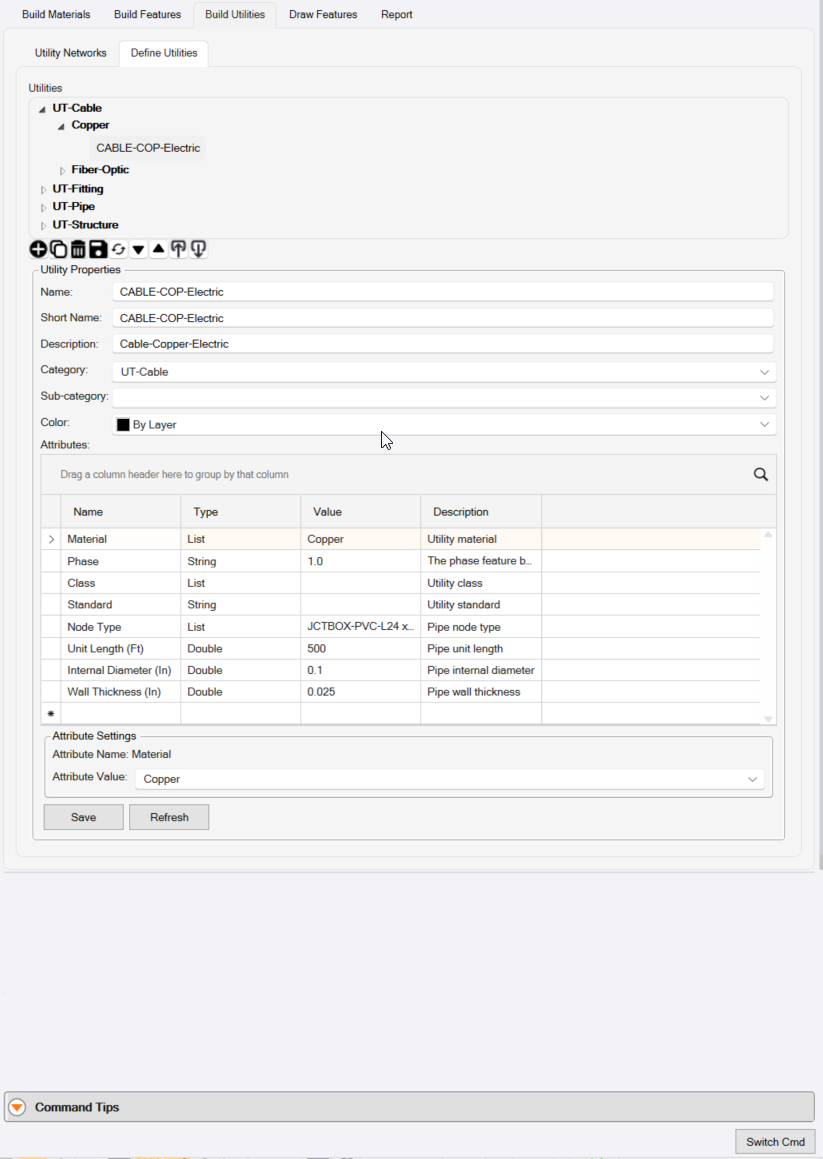
Utility Features are not defined with any connection to a specific Utility Network. When you create a Utility Feature, you will associate a specific feature to a specific Utility Network at that time. In this way you can use e.g. a speciic Pipe Feature for both a Storm and Sanitary Network, saving you from having to deine the Pipe Feature multiple times for different Utility Network use cases.
Utility Features are automatically divided into the following Categories (defined using RPS Settings - Smart Feature Settings).
- UT-Cable
- UT-Fitting
- UT-Pipe
- UT-Structure
These categories already have Sub Categories as follows (defined using RPS Settings - Smart Feature Settings).
- UT-Cable has Copper and Fiber-Optic Sub Categories
- UT-Fitting has Bend, Coupler, Expander, Hydrant, Meter, Stop, Tee, Thrust Block, Valve and Y Sub Categories.
- UT-Pipe has Arch, Box Culvert, Circular, Elliptical-Horizontal, Elliptical-Vertical and Rectangular Sub Categories
- UT-Structure has Box, Cylindrical, Null (No Structure) and Terminal (Headwall, Endwall) Sub Categories.
Every Utility Feature that you define has a set of common properties including the following
- Name
- Short Name
- Description
- Category
- Sub Category
- Color e.g. By layer (Use this by default) or a Specific Color
Fitting Features will also allow you to define
- Reference Block Check Box
- Select the Block from the list of available Blocks (CAD Blocks)
- Block Scale - Enter the scale / size that you want to make the block on the drawing
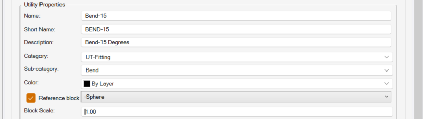
When you create the Fitting, the Block will be placed at the Fitting Location in 2D or 3D to represent the presence of the fitting at that location.
Feature Attributes
Every Feature that you define can have Attributes. Attributes can be System Assigned or they can be User Defined.
System Assigned Attributes are attributes that are required to define the shape, size or materials of a feature. For example
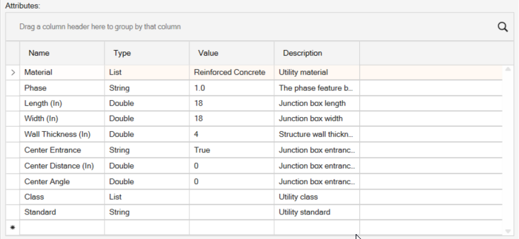
- A Box Structure requires a Rim and Invert Elevaion, it also requires a Width, Length and Wall Thickness as well as a Material e.g. Reinforced Concrete as well as a Class, maybe a defined Standard and whether the Entrance Cover will be on Center or not, and if not then a Distance from the structure Center to the Entrance will be required etc.
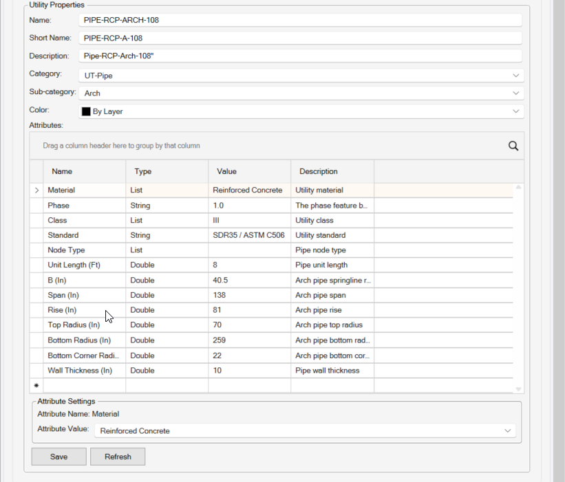
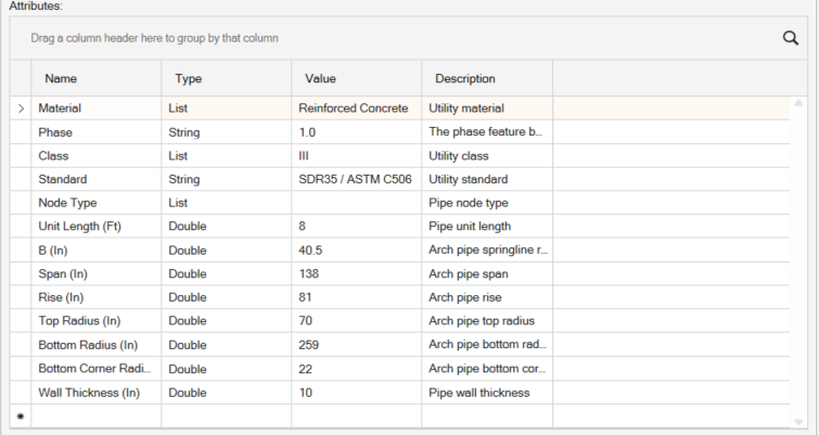
- An Arch Pipe requires a Span and Rise, the B Spring Rise, the three radii as well as the wall thickness and unit length of the pipe and the pipe material along with the Class and optional Standard that defines the pipe.
User Defined Attributes can be defined to supplement the system assigned attributes to adequately define the features for reporting purposes. All attributes will be displayed in the properties Pane for the feature when it is selected, and those relevantt to a Takeoff Report will be reported accordingly.
Some of the attributes can be entered or selected directly in the Attribute Grid, otheres when you select the attribute, will have the Attribute Settings below the grid whene you can enter the values or select the attribute required. Once selected or entered, the grid will update to displaye the selected or entered values.
Many standard pipe types, culvert types, structure types have alreay been defined in the default RPS Feature Library. Review the different utility features to gain an understanding of how each utility feature is defined. Here are a few examples
Arch Pipe
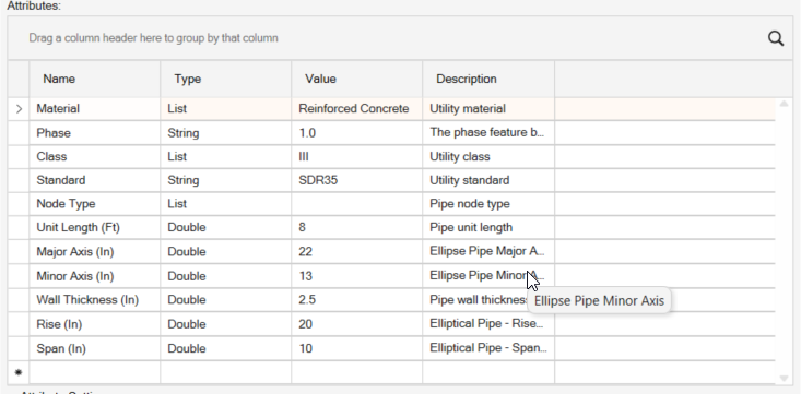
Elliptical Pipe - Horizontal
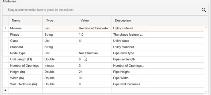
Box Culvert
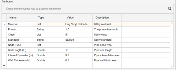
Circular Pipe
Box Structure
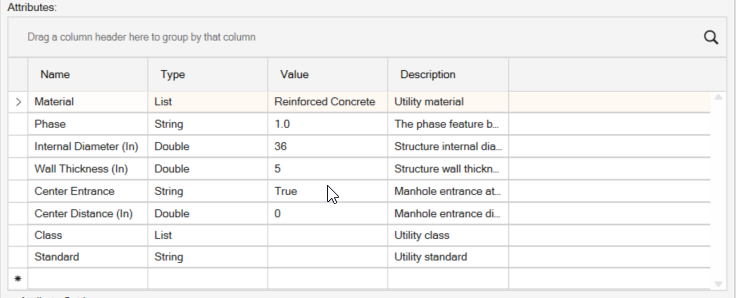
Concentric Manhole
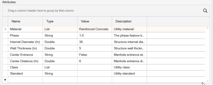
Eccentric Manhole
Draw Features
For Draw Features Documentation - Click here
Naming Recommendations
As in many things TBC. we highly recommend that you develop a good naming convention for Smart Features, Categories, Sub Categories, Materials etc.
With the new tools provided in RPS Command Library 2026.1, you have better search capabilities and filtering capabilites than ever when you are trying to select a Smart Feature. Using consistent names and abbreviations can really help you to find things quickly - some examples include
ASPH = Asphalt
CONC = Concrete
PVMT = Pavement
FG- = Finished Grade
EX- = Existing Ground
EROS- = Erosion Control
DEM- = Demolition
CADXS- = CAD / PDF Section
CADPR- = CAD / PDF Profile
UTIL = Utility
CIRC = Circular
ARCH = Arch
RECT = Rectanular
-A = Area Feature
-LW = Length Width Feature
-LA = length Area Feature
-L = Length Feature
-C = Count Feature
GENERIC = Generic Feature
HD = Heavy Duty
LD = Light Duty
Header Bar Commands
In the header bar of the command you will find icons that provide quick ccess to other key RPS Smart Suite commands as well as other command that you may find useful while running this command.
Header Bar commands include the following
- Command Pane
- Lock / Unlock the Command Dialog
- RPS Help
- RPS Settings
- PDF Manager
- CAD Cleanup
- Smart Select
- Smaret Draw
- Smart Edit
- Smart Elevate
- Smart Profile
- Smart Model
- Volumes Manager
- Smart Takeoff
- Smart Plot
Command Tips
The Command Tips section of the dialog provids you with access to the command help documentation (this document). It also provides you with any Tips, command shortcuts etc. that may be helpful to yiou when running this command.
Command Controls
Switch Cmd
The Switch Command function allows you to
- Close the current command
- Close All open Commands
- Switch to another RPS Smart Suite Command that is currently running in the background
The ESC key also acts as a Smart Switch conytrol, and pops up the list of all currently running Smart Suite commands as well as the ability to Close the Current or Close All Commands right on your current cursor position.
Smart Feature Tips and Tricks
Using Region Track to Create Smart features
We recommend that when using the Region Track function to create new Area Features that you do not offset the Region line being created. Subgrade Models will work best when you create your Feature edges exactly along lines that are also used in the Finished Grade Model.
Hot Keys
The following hot keys are available while using the Smart eature command in the Build Features modes.
Function Hot Keys
N = New loop / selection
Z = Toggle Z Formula On / Off
X = Abort current creation and start a new creation
SHIFT X = Cancel / remove prior node
J = Join to line (hover over line to join and press J key)
G = Rock Grips
F = Select a new feature
CTRL + Left Click = Draw Arc (CTRL + Click Several Points = Smooth Curve)
Create Features - Mode Shortcuts
Assign Feature = A
Copy To Create Feature = C
Draw Feature = D
Region Track = R
Shrink Wrap = S
Track = T
Use Case Videos
The following videos show the use of the Smart Feature command in a work process context
Feedback and Enhancement Requests
If you would like to provide feedback on the use of the Smart Feature command or to request enhancements or improvements to the command please click Reply below