RPS Smart Profile

Command Licensing and Default Menu Location
- The Smart Profile command is part of the Smart Suite Command Library
- The command is located on the Smart Suite menu ribbon
- The command can be found in the Takeoff menu group
Command Description
Provides the ability to convert profile drawings imported from CAD or extracted from PDF files into 3D linestrings, vertical alignments for alignments, utility pipes and structures, 3D linework for MSE and retaining walls. The calibrated profile drawings can also be used to check horizontal, vertical and Slope distances, slope % of lines (e.g. Sewer Pipes), and to determine depth of cover, pipe lengths within defined depth brackets, clearance and areas of excavation.
Release History
Dec 2025 - first release as a part of the RPS Command Library 2025.4 release
Video Demonstration
The following video shows how to utilize the Smart Profile command
Command Interface Description
The Smart Profile command dialog looks as follows
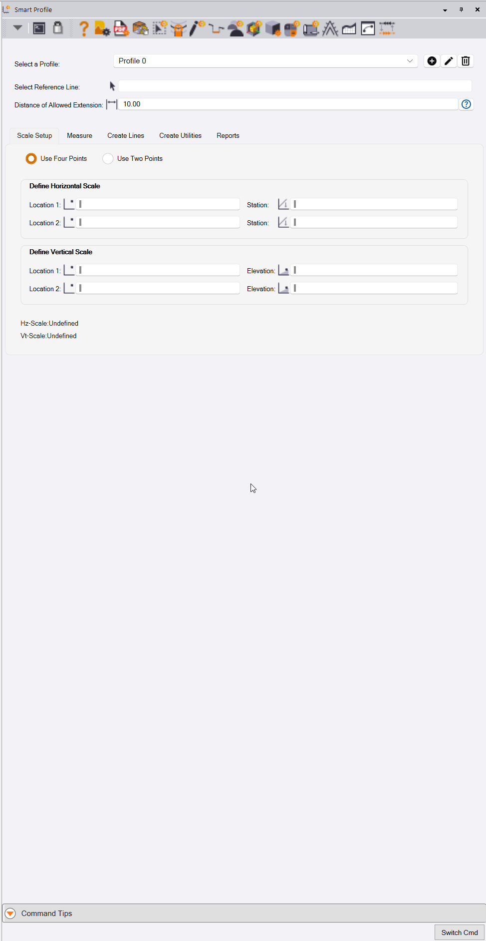
The command interface provides a 5 step work process, broken out into tabs to provide easy to follow steps.
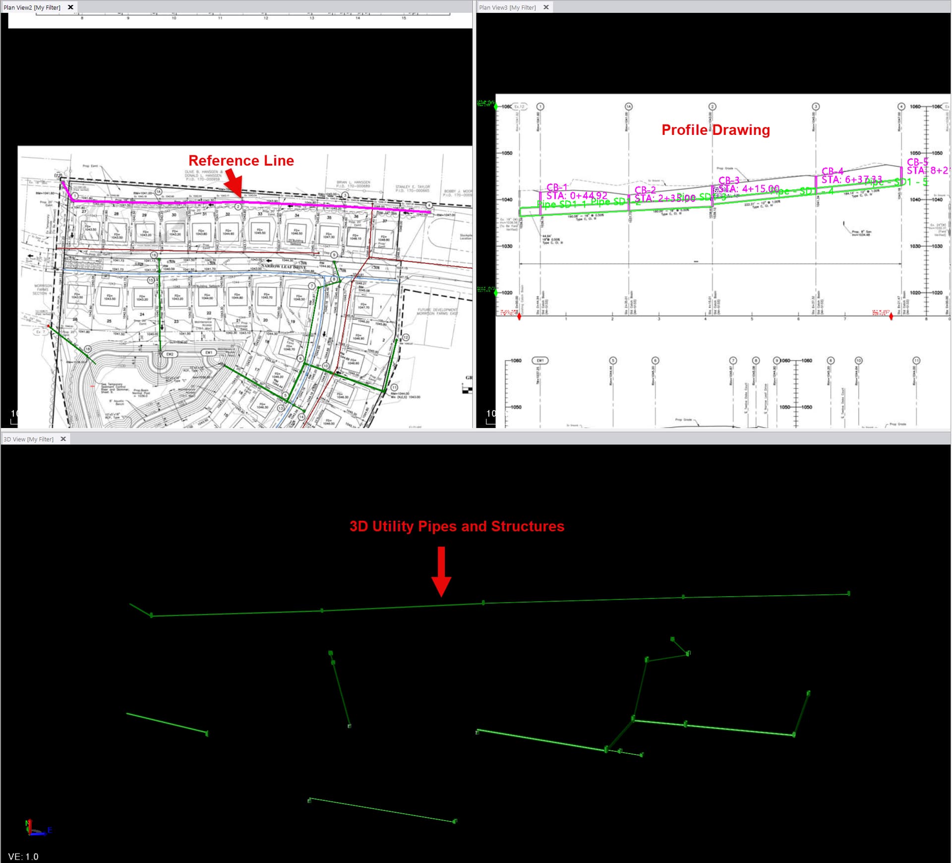
Step 1 - Scale Setup - Create calibrated profile drawings and connect the profiles to plan view reference lines.
Step 2 - Measure - Take length, slope, elevation differences, running distances, depth of cover and pipe length depth brackets directly from the profile drawing and save measurements into the integrated spreadsheet reports.
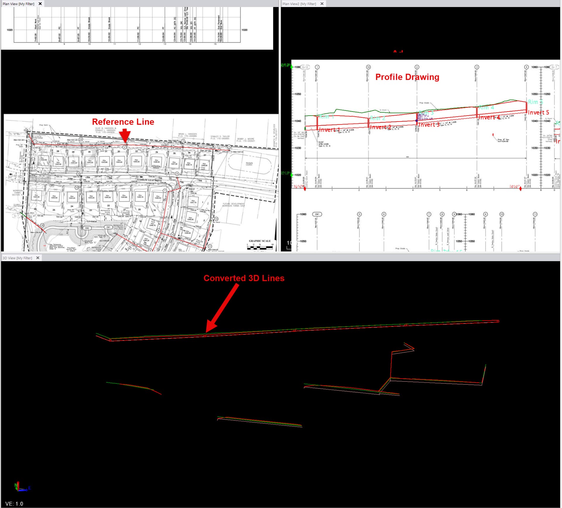
Step 3 - Create Lines - Convert the 2D profile drawing linework into 3D lines along the path of the connected reference line.
Step 4 - Create Utilities - Assign utility pipe and structure features to the profile drawing linework, and convert the profile drawing into 3D pipe and utility structures.
Step 5 - Reports - Review and print the computed measurements from Step 2 in the integrated spreadsheet reports.
Pre-Requisites
Before you can use the Smart Profile command, you will need to have first imported either a CAD file or a PDF file that contains one or more profile drawings. You will also likely need plan view linework that represents the features along which the profile drawing was created.
The profile drawings can contain any of the following types of information
- Road vertical alignment along with ground and finished grade profiles
- Storm, Sanitary, Water or other utility profiles containing pipe and structure details
- MSE or Retaining Wall details
- Foundation details
In all cases the profile drawing will have Stationing along the X axis and Elevation along the Y axis along with linework that represents the features that you want to measure or model. The profile drawing can be a traditional profile drawing with the axes clearly drawn and labeled, or can be an elevation drawing that has at least one horizontal distance and 2 elevation points marked so that the profile can be calibrated for Station and Elevation and so that vertical exaggeration can be determined and accounted for in any measurements of length, area, elevation etc.
The Profile drawing will have been placed / created in the plan view of TBC.
Create the Smart Profile
Before you begin the workflow, create the Smart Profile definition.
Select / Define a Profile
You can create, edit and delete a profile definition. Once profiles have been defined, select the one that you want to work with here. The profiles are stored in the VCE project file so that they can be recalled at any time to take additional measurements and add to the Smart profile reports.
Click the ![]() button to create a new profile.
button to create a new profile.
Click the ![]() button to edit the name of the currently selected profile
button to edit the name of the currently selected profile
Click the ![]() button to delete the urrently selected profile
button to delete the urrently selected profile
Select Reference Line
If you want to flip the profile drawing into 3D linework or into 3D pipes and structures, select the plan view line that represents the path of the profile drawing.
Notes:
The path of the line needs to have the same 0 station start point as the profile drawing, and the same length or longer as the profile drawing, for the two sets of data to be correctly correlated.
The path of the line needs to also be drawin in the same direction as the profile drawing, reverse the line if this is not the case.
Distance of Allowed Extension
In some cases, there may be additional details in the profile drawing that extend beyond the 0 and max station ends of the profile drawing. You can enter a distance value into this field to allow the extension elements to be projected onto the selected plan view linework as extensions to the selected line. An example would be a Storm Sewer Run where at one end there is a headwall that has a Rip Rap area that starts before the 0 station of the profile drawing.
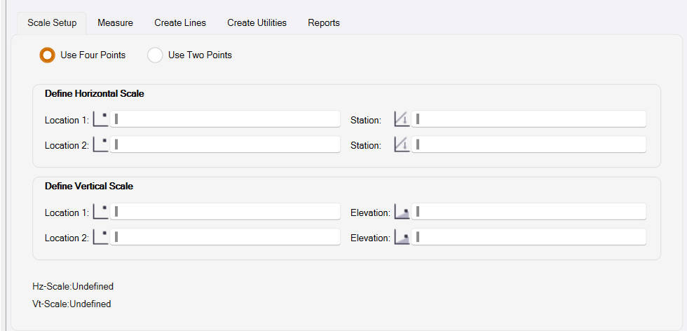
Step 1 - Scale Setup
You have two options for defining your scale on your profile drawings
- Use Four Points (2 Station points and 2 Elevation points)
- Use Two Points (Each point has a Station and Elevation value)
Below we will look at each in detail.
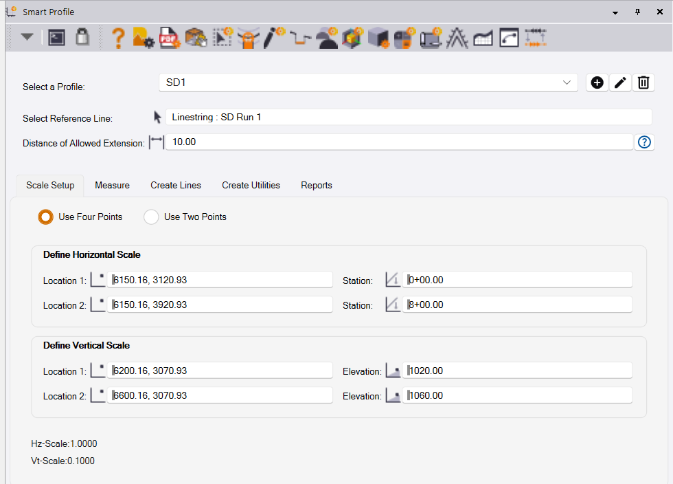
Scale Setup from Four Points
In this section of the dialog you will define your Horizontal and Vertical scales separately. To start you will choose two points on the horizontal scale or X axis of the profile grid. For each point you will define a station value associated with that location on the grid.
For the Vertical scale you will choose two points on the vertical scale or Y axis of the profile grid. For each of those points you will define an elevation value associated with that location on the grid.
On completion of the process, the computed Horizontal and Vertical Scale will be displayed so you can check the results before continuing.
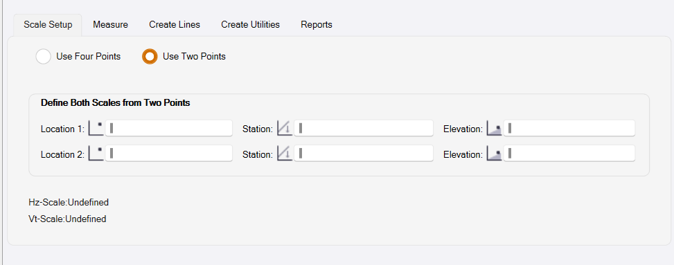
Scale Setup from Two Points
In this section of the dialog you will define your Horizontal and Vertical scales in tandem. To start you will choose two points that differ in both the Horizontal and Vertical values i.e. you cannot select two points with either the same station or the same elevation values. With each point you will enter a Station and Elevation value for that point.
For instance, you might choose the first point at the bottom elevation of your profile grid and at the starting station. When you define your second point you might choose the top elevation and the ending station for that profile drawing. Doing this will allow the command to compute both the horizontal and vertical scales of the drawing and display them to you.
By completing either the Four Point or Two Point setup you will have defined the scale for that profile drawing, and may then use the measure or conversion tools on this profile. After completing a scale setup it is recommended practice to do a single point measurement somewhere on your profile to ensure that the correct station and elevation values are displayed to you. If you notice error in either value you should examine your scale setup and try to redefine the affected scale.
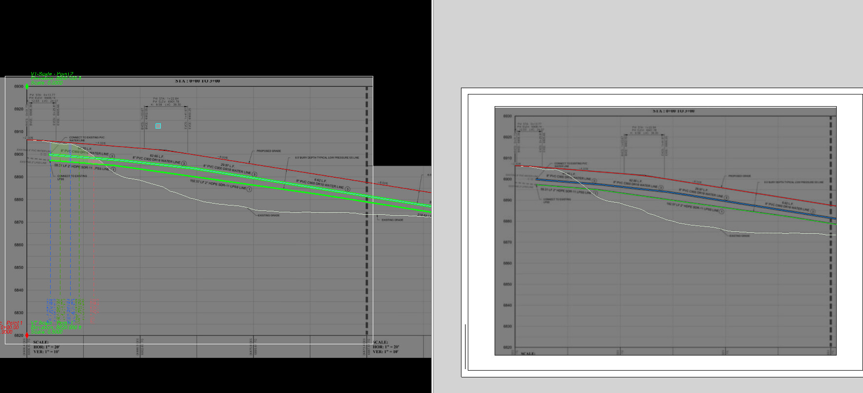
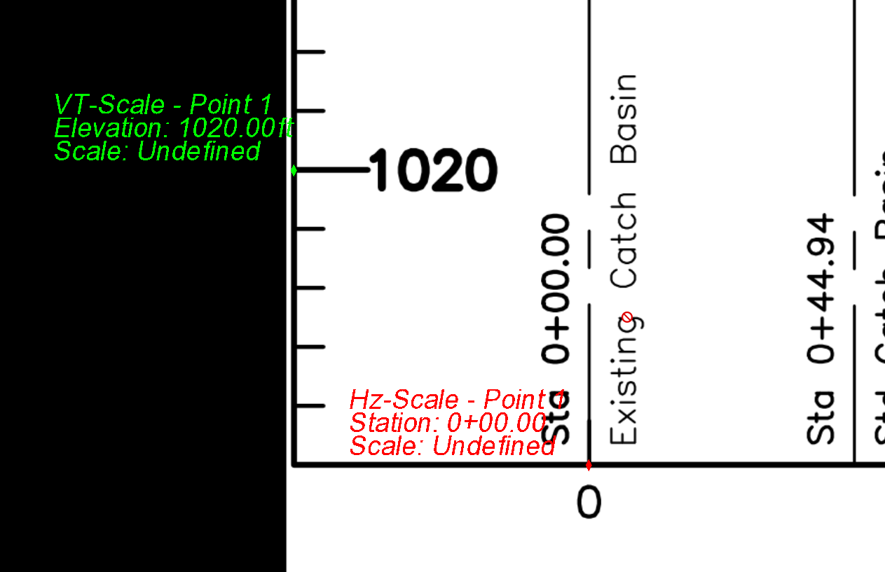
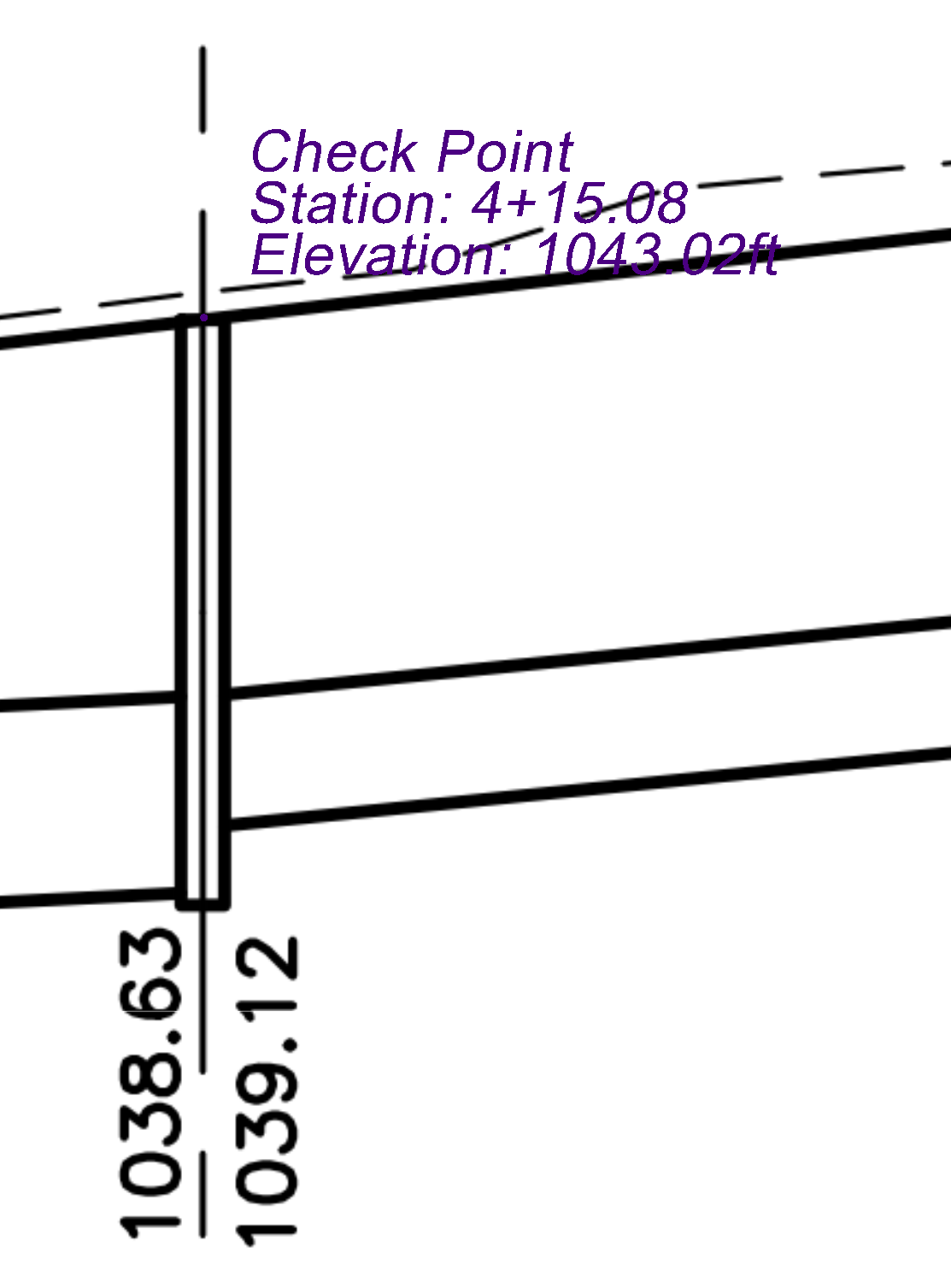
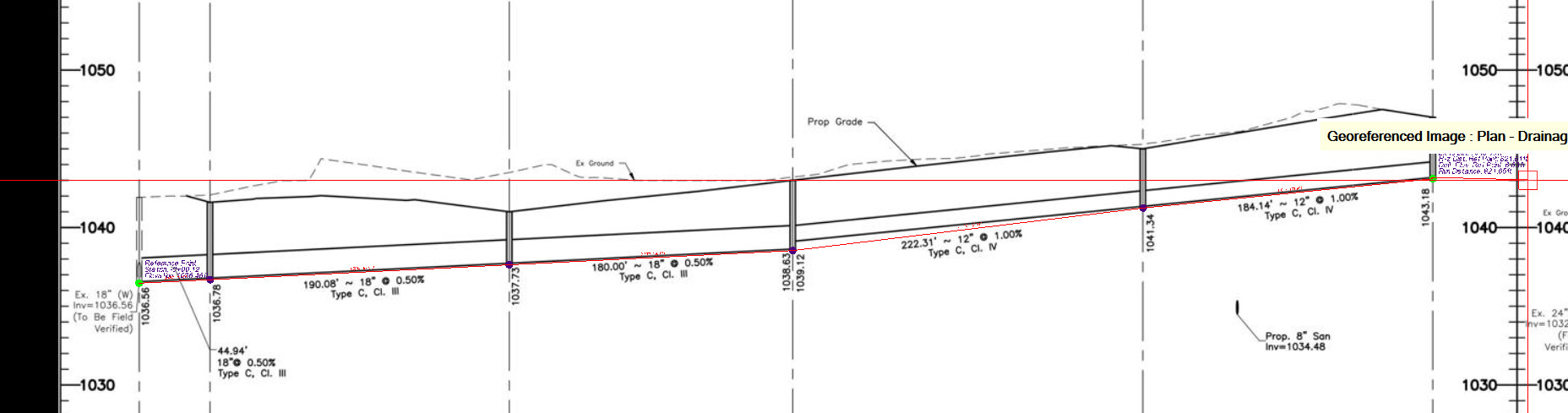
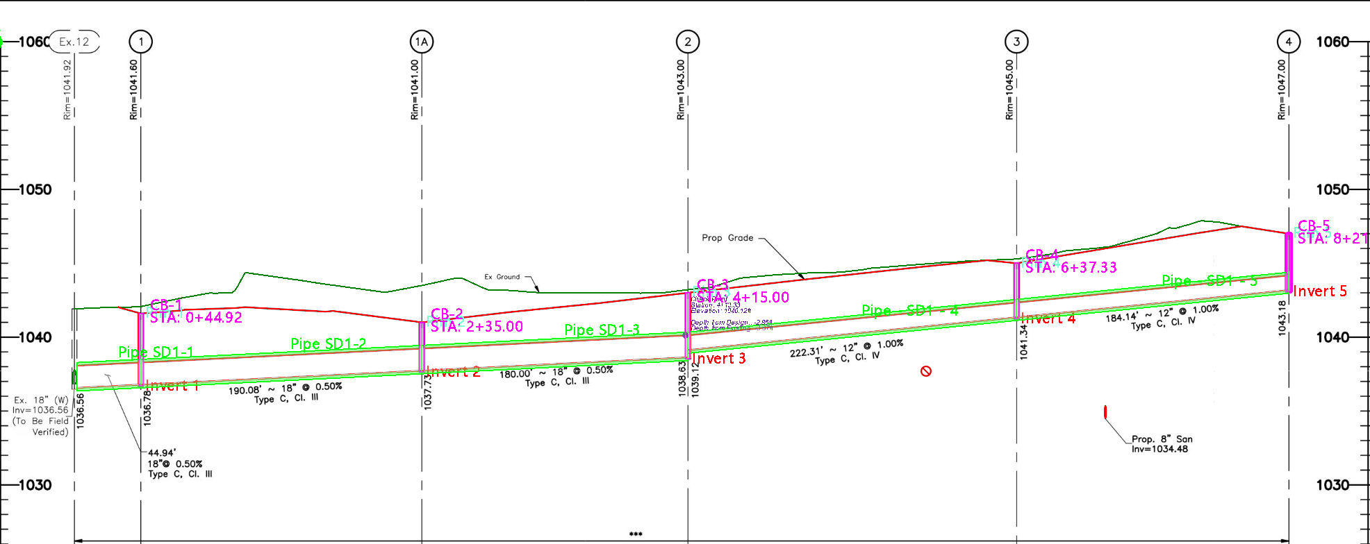
Once computed, the calibration for the profile is stored within the project so that it can be easily recalled when needed. The calibration points for the profile will be displayed on the profile drawing as follows
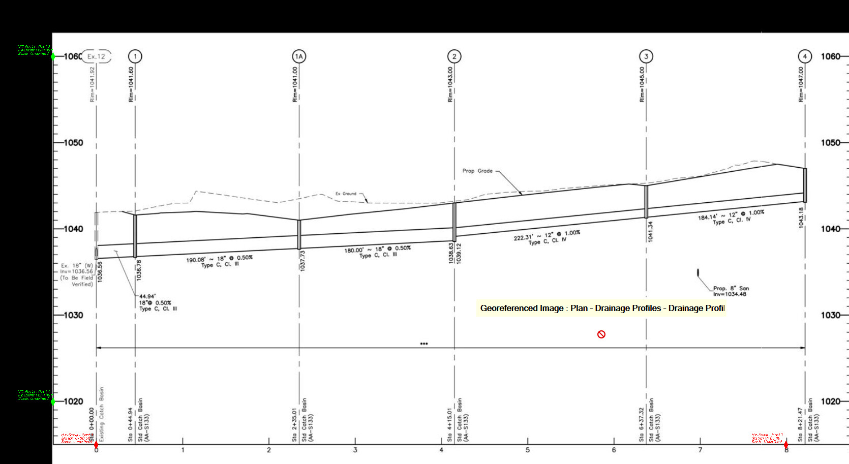
You are now ready to either make measurements from the profile, or to convert the profile linework into 3D linework, or 3D utility pipes and structures.
Step 2 - Measure
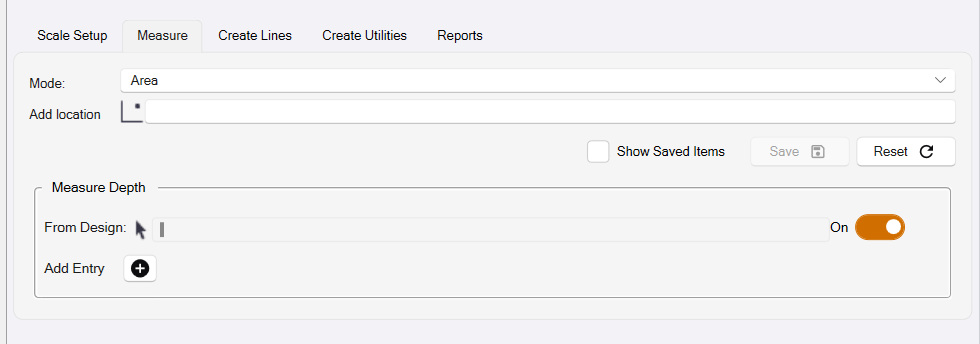
The Measure process dialog looks as follows
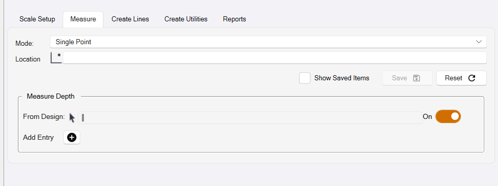
Mode
The first step is to select the measurement mode that you want to use, the options are
- Single Point - measure / check the Station and Elevation of a profile location
- Two Point Distance - measure / check the distance between two profile locations. The measurement includes horizontal, vertical and slope distances as well as the slope between the two locations.
- Reference Point Distance - measure / check the distances between a constant reference point and two or more profile locations. Each location that is clicked will display an updated set of results for the new baseline (Ref Point to Location). Each measurement includes horizontal, vertical and slope distances as well as the slope between the two locations.
- Running Distance - measure the running distance between multiple locations along the profile drawing. The measurement includes the running horizontal, vertical and slope distance as well as the slope between the first and last locations.
- Area - measure / check the area enclosed by a drawn line in the profile to capture the base data for e.g. trench volume calculations.
- Depth Brackets - Analyze the depths between two selected lines in the profile drawing e.g. Finished Grade and Base of Trench, using defined depth brackets to determine the length of pipe in the profile that falls within the different depth brackets applied.
As each measurement is created, you can click the Save button (or Hotkey S) and provide a name for each measurement that will then create a measurement record in the integrated spreadsheet report - accessed from the reports tab of the command.
Once measurements have been saved, they can be displayed on the profile drawing by checking the Show Saved Items checkbox.
If you wish to clear the measurements and start over, click the Reset button.
In addition, you can also measure depth of cover / clearance in the profile to one or more of the profile drawing lines (e.g. from Finished Grade and Existing Grade to top of pipe or bottom of pipe etc. in the profile).
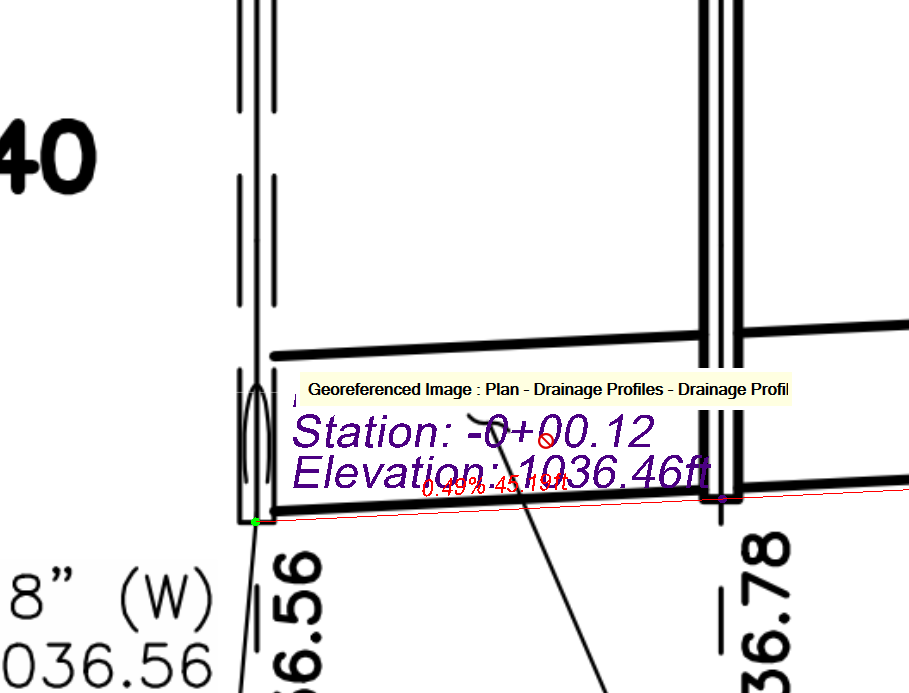
Single Point Measurement
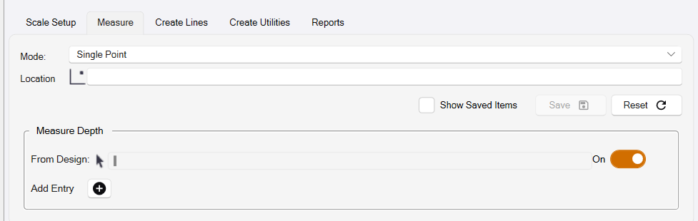
This measurement tool allow you to get Station and Elevation information for the chosen location as well as any depths that you have defined in the section below this.
Click the location that you want to derive the measurement at. Note that if you are working with Vector PDF data or CAD data, you can snap to vector locations in the profile image or to TBC Snap locations on displayed TBC objects. Use the TBC Snap controls to enable the required snap functionality for the most precise measurements.
Two Point Distance
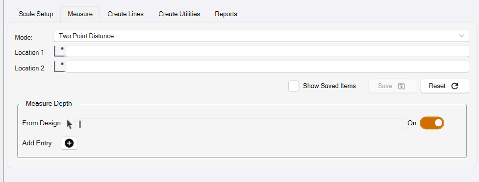
The Two Point Distance measurement will allow you to report various distance measurements between two points in the drawing. These values include: Slope, Horizontal Distance, Slope Distance, and Vertical Delta.
Click location 1 and location 2 to establish the masurement.
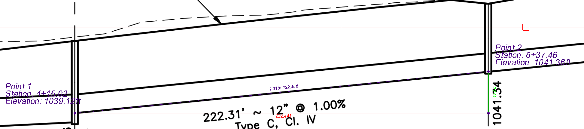
Reference Point Distance
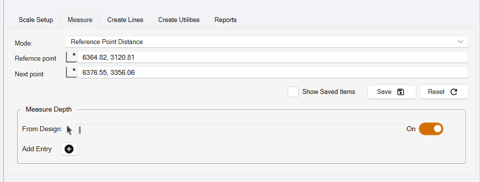
The Reference Point Distance measurement will allow you to report various distance measurements between the reference point and a chosen point in the drawing. These values include: Slope, Horizontal Distance, Slope Distance, and Vertical Delta. When multiple measurements are made in sequence, the reference point remains and a new “Next Point” is defined.
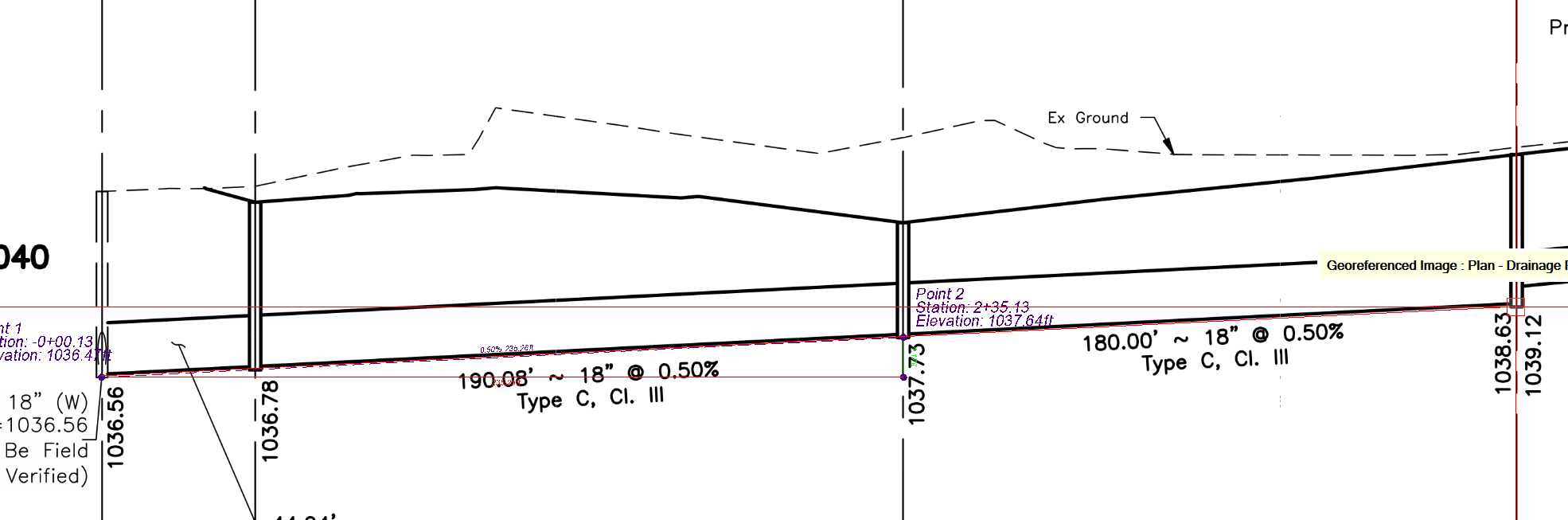
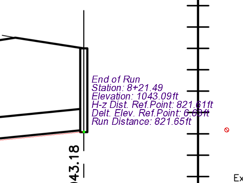
Running Distance
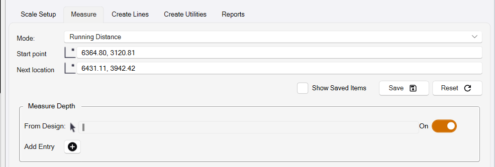
The Running Distance mode measurement will allow you to take a series of distance measurements that total up as you measure each subsequent point. This can be useful for preforming quick takeoff calculations from a set of profile drawings.
Click the Start point and then a series of next points to create the running distance calculations.
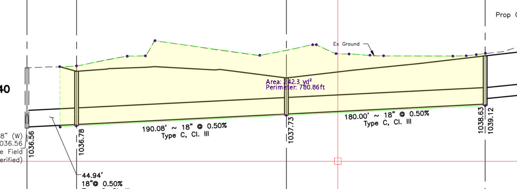
Area
The Area measurement will allow you to draw a polygon shape onto your profile drawing that will allow you to report area and perimeter values for the drawn polygon.
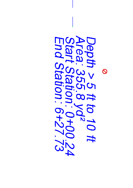
Depth Brackets
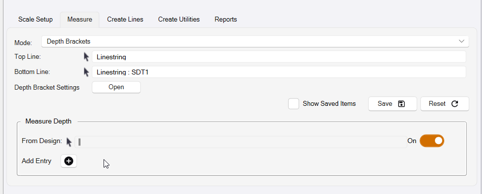
The Depth Brackets measurement will allow you to calculate areas between two selected lines based on your defined depth bracket settings. This can be used to calculate the lengths of pipe that fall within each depth bracket, based on either an original ground line or finished grade line and the base of trench line of your utility run.
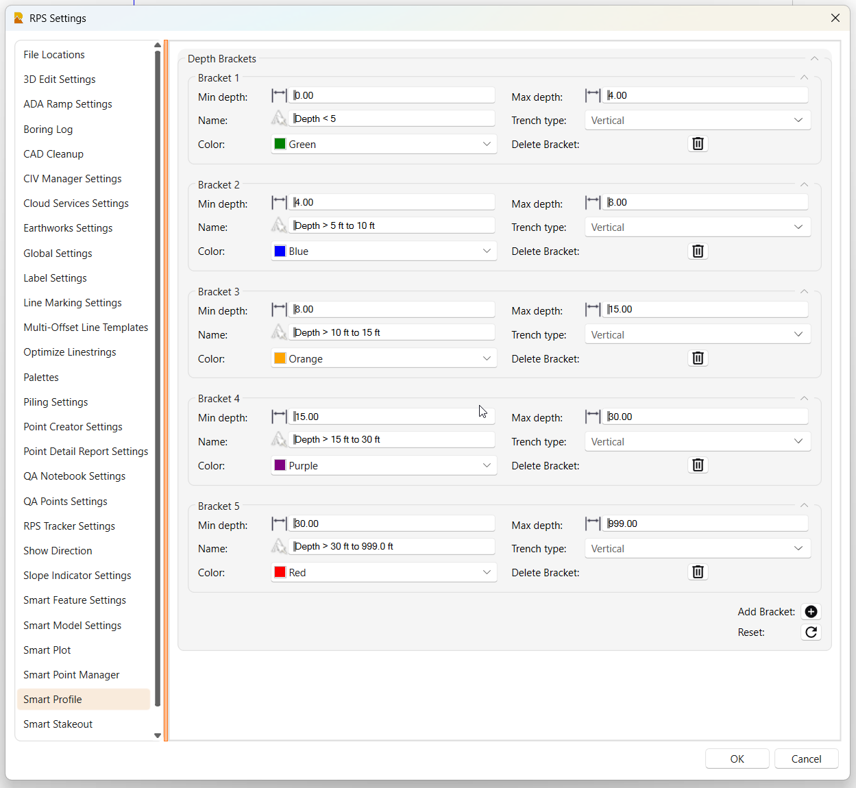
Depth Bracket Settings
The Depth Bracket settings are created and stored in RPS Settings for the Smart Profile command. Click the Open button next to the Depth Bracket Settings dialog element to access the Depth Bracket Settings dialog of RPS Settings.
Use the ![]() Add Bracket button to add a new depth bracket
Add Bracket button to add a new depth bracket
Click the ![]() Reset button to return the depth brackets to the defualt configuration
Reset button to return the depth brackets to the defualt configuration
Click the ![]() Delete button to remove a depth bracket
Delete button to remove a depth bracket
Each depth bracket has the following elements
Min Depth - the low end of the depth bracket e.g. 0’
Max Depth - the high end of the depth bracket e.g. 5’
Name - The depth bracket name e.g. Depth <5
Trench Type - The walls of the trench (Vertical, Sloped or Benched) (currently unused)
Color - The color of the depth bracket that will be used for the areas in the profile drawing
Notes:
Each depth bracket builds on the previously defined depth bracket, i.e. if the first bracket ends at 5’ then the next bracket starts at 5’ automatically.
There are no limits to how many depth brackets you can create.
Measurement Hotkeys
For Each of these described measurements, you may choose to save using either the “S” key shortcut wired into this command or clicking the save button. If you would like to see previously saved measurements in the graphics check on the “Show Saved Items” toggle. Saved measurements will also be added to your Measurement Report.
Measure Depth
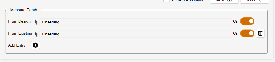
The measure depth function supplements the other measurements with additional depth measurements from one or more designated lines that represent fetures like Existing Ground or Finished Grade or Bottom of Subgrade or maybe a Strata layer like Rock.
Each additional entry is given a name like Existing Ground or Subgrade or Rock Strata etc.
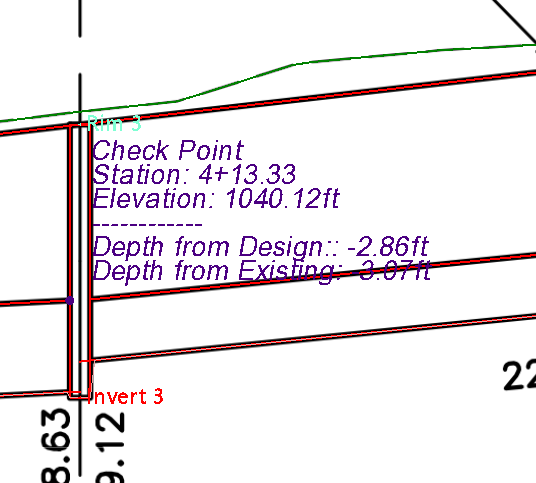
When you take e.g. a Single Point measurement, the results will now look as follows, in this case displaying the Depth from Design and Depth from Existing surfaces at the measurement point.
Step 3 - Create Lines
In the Create Lines process, you have two options
- Create Multiple Lines - will convert any number of lines in the profile drawing into 3D lines along the profiles reference line.
- Create Vertical Alignment - will convert a single profile line into a vertical alignment for a selected horizontal alignment.
Create Multiple Lines
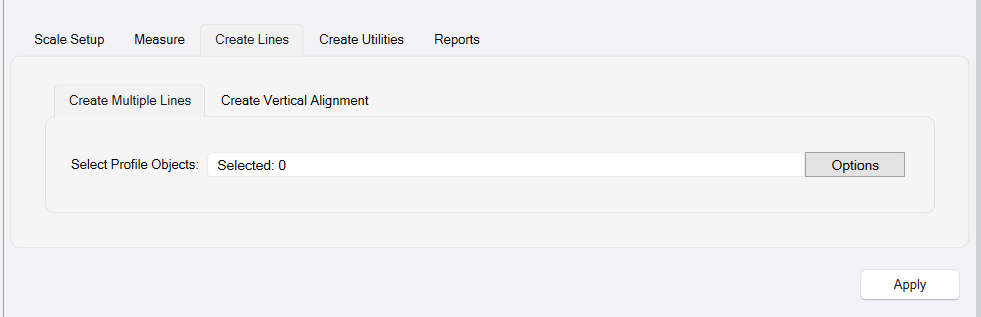
Select Profile Objects
Select one or more lines in the profile drawing that you want to convert into 3D lines. The lines that you select can be horizontal, vertical or variable shape along the length of the profile.
Apply
Once the lines that you want to convert have been selected, click the Apply button to execute the process.
Create Vertical Alignment Mode
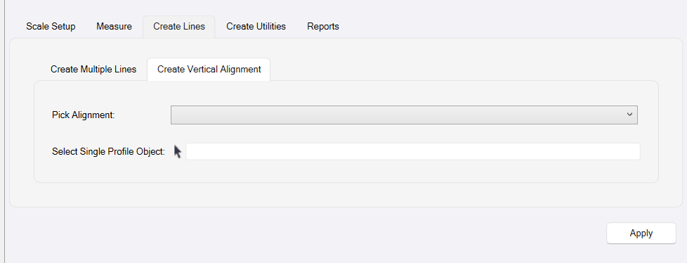
In this mode you will select a single Horizontal Alignment and a Single Profile Line that represents a Vertical Alignment for the Horizontal Alignment and then click Apply to convert the profile into the vertical alignment.
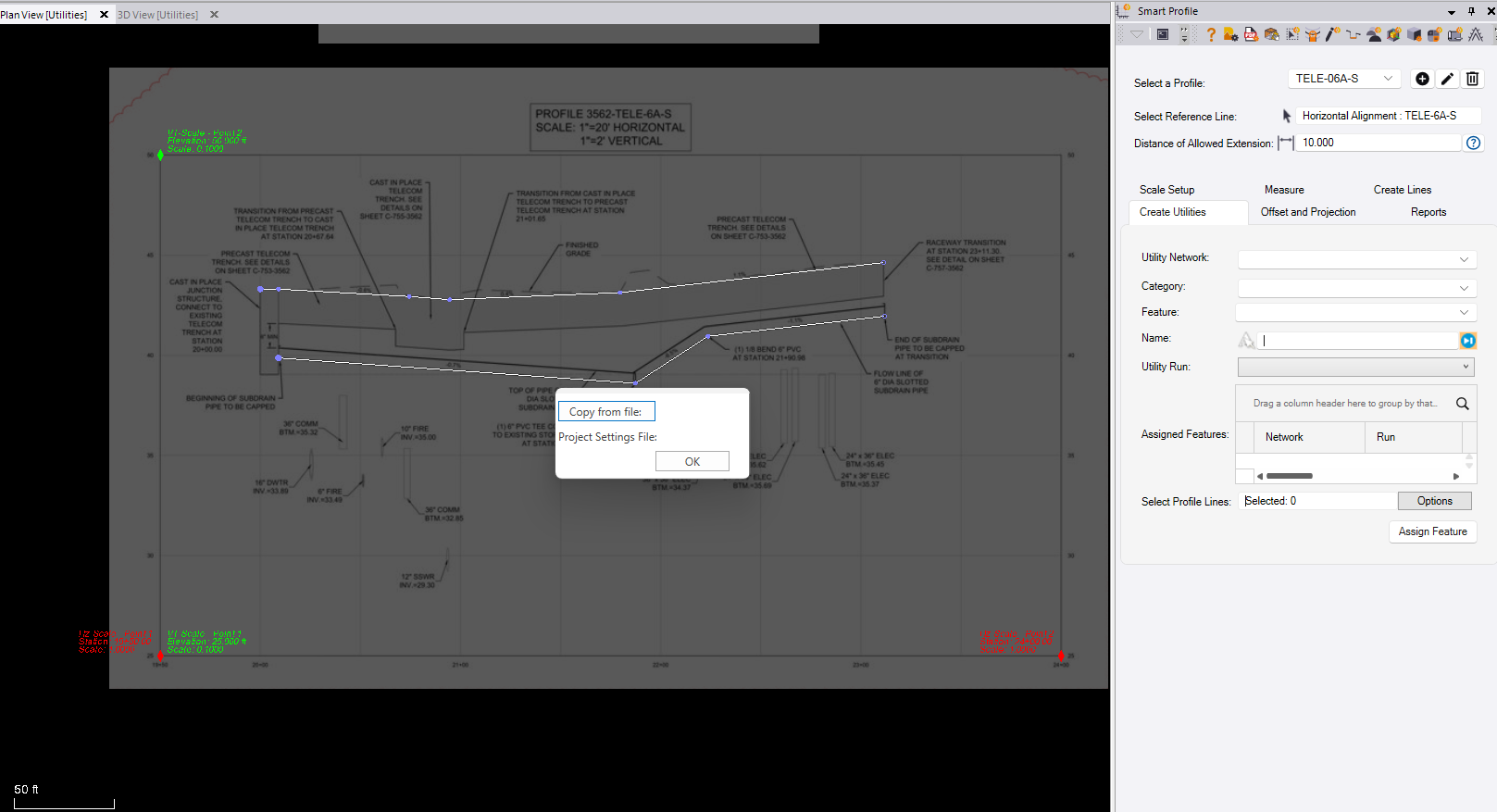
Step 4 - Create Utilities
In this step you will “Featurize” lines in the profile drawing as utility pipes or structures. The process requires the use of an RPS Smart Feature Library. The Smart Feature Library will be created using the Smart Feature command. This allows you to define Utility Networks (Storm Sewer, Sanitary Sewer. Water etc.), and Utility Features including Pipes, Cables, Structures and Fittings. In Smart profile, you will assign Smart Features to lines in the profile, so that on conversion to 3D they will become the 3D Features and be displayed as pipes and structures.
A pipe feature will typically be defined using the invert line of the pipe in the profile drawing. You may need to extend the profile lines so that they extend into the center of the structures placed at each end of the pipe. Use the Trim / Extend line function of the Smart Edit command to handle this requirement.
A structure feature will be defined as a closed polygon shape in the profile drawing eg a rectangle or a concetric or eccentric manhole etc.
You must first run the Smart Feature command and load a Smart Feature Library into the project.
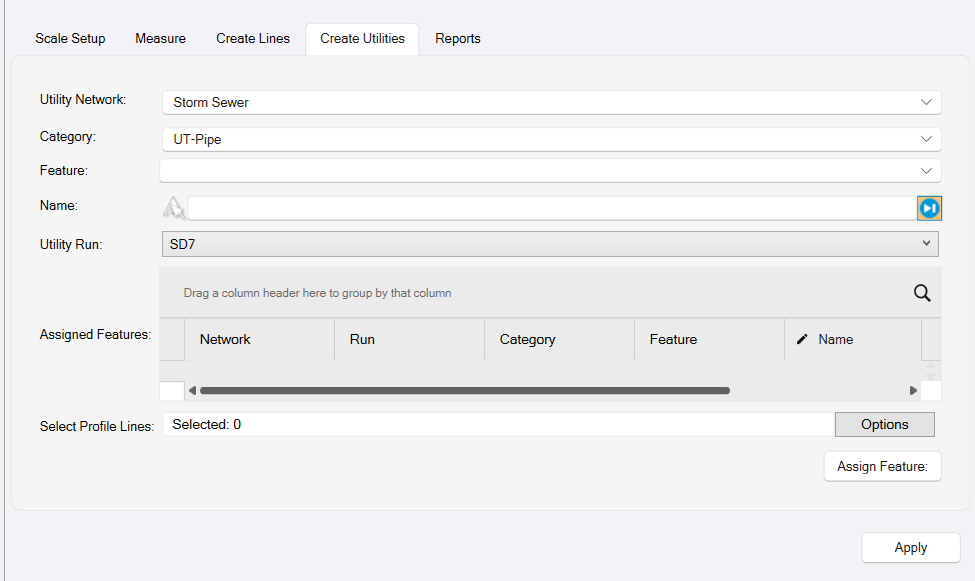
Utility Network
Select the Utility network that the profile drawing belongs to. The profile drawing will be a Run in that selected network. The Utility Networks will be defined in the Smart Feature Library by the Smart Feature command.
Category
In the Smart feature Library, Utility Features are grouped into Categories e.g. UT-Pipe or UT-Structure. Select the category inside which the features you will be assigning are defined.
Feature
Select the Feature from the list of available features that are defined within the Category that you selected. e.g. PIPE-RCP-Circ-12 would be a 12” RCP Circular Pipe.
Name
Input a name for the feature that you are creating e.g. Pipe 1, Pipe 2, Catch Basin 1, Drainage Inlet 1 etc. You may want to combine the Run and Object name together i.e. if you are defining Storm Drain Run 1, and this is the first pipe in Run 1 you may use PIPE-R1-1 etc. It is beneficial if each Pipe and Structure has a unique name.
Utility Run
In TBC the structures of a network belong to the network, the pipes of a network belong to a run in the network. A single structure could be utilized in 2 or more runs, hence the reason that the structure belongs to the network. A pipe can only belong to a single run, hence the reason that the pipe belongs to a run in the network.
By default, the Utility Run name is inherited from the profile name. If you are currently working on profile Storm Sewer 1, then the Utility Run name will be Storm Sewer 1 to match. If you want to create your own run name, pull down the list and select “New” at the base of the list to create a new Run name.
Assigned Features
Select the line in the profile drawing that represents the feature that you are assigning. Click the Assign Feature button to complete the process for each line that you are featurizing. Then repeat the process for each successive pipe or strucrture, until you have assigned all of the profile lines to features as neeeded. The features as they are assigned will be displayed in the grid beside the Assigned Features title.
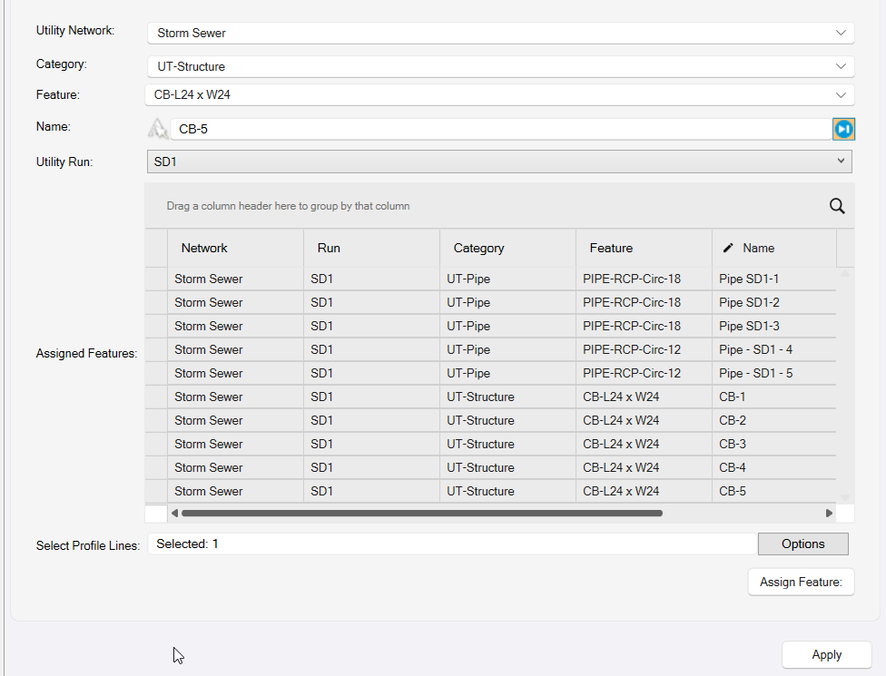
Note that in the grid, the Station values are displayed. If the values displayed do not fully agree with the plans you can adjust the values by eiting the values displayed in the grid. Click in the cell that you wish to edit, make your changes and then tab out of the cell to complete the edit.
At this time you can only edit the Station Values of the Structures. Elevations cannot be edited at this time.
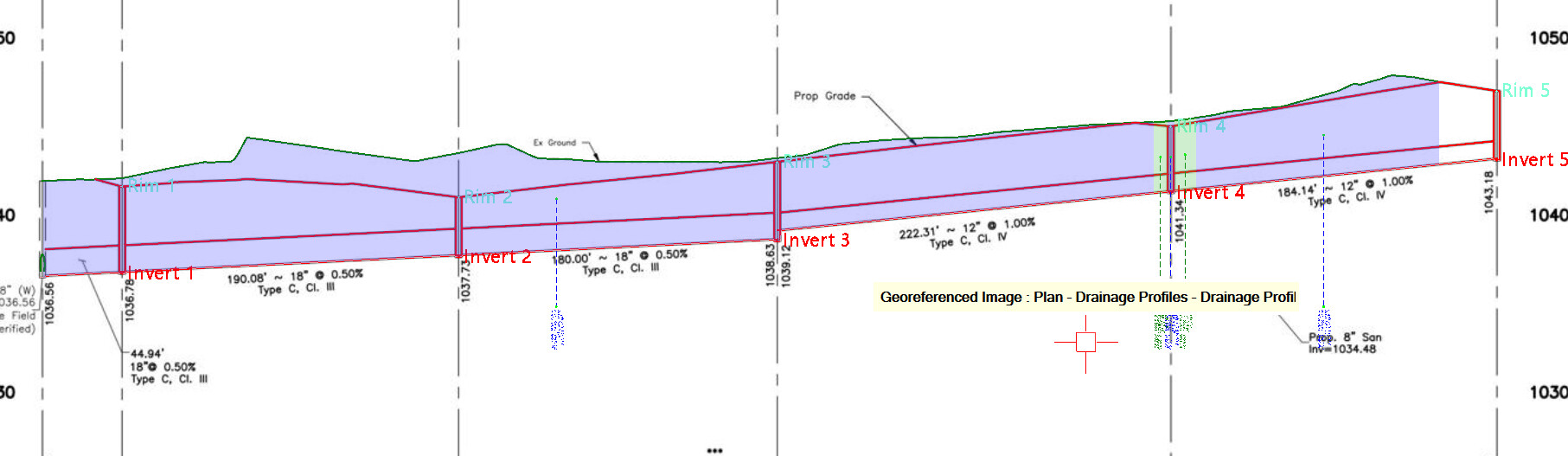
The pipes and structures will be drawn over the profile view as shown below as a check that you have assigned the correctly sized features. The structures will also be displayed with a shape that indicates a box structure, concentric or eccentric manhole or a headwall / endwall structure.
When all the Features have been assigned, click the Apply button
Step 5 - Reports
The reports tab houses the integrated spreadsheet report. This stores all of the measurements made using the profile drawings. There are multiple tabs in the reports pane, one for each type of measurement i.e.
- Single Point
- Two Point Distance
- Reference Point Distance
- Running Distance
- Area
- Depth Brackets
If you also made measurements using the Measure Depth function, then the supplemental measurements can be found in additional columns of each report. Here are a few example reports
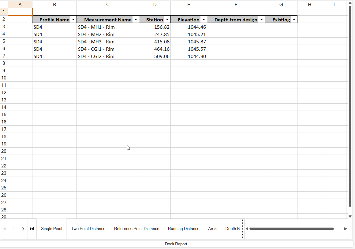
Single Point Report e.g. for Rim and Invert Elevations and Structure Height Determinations
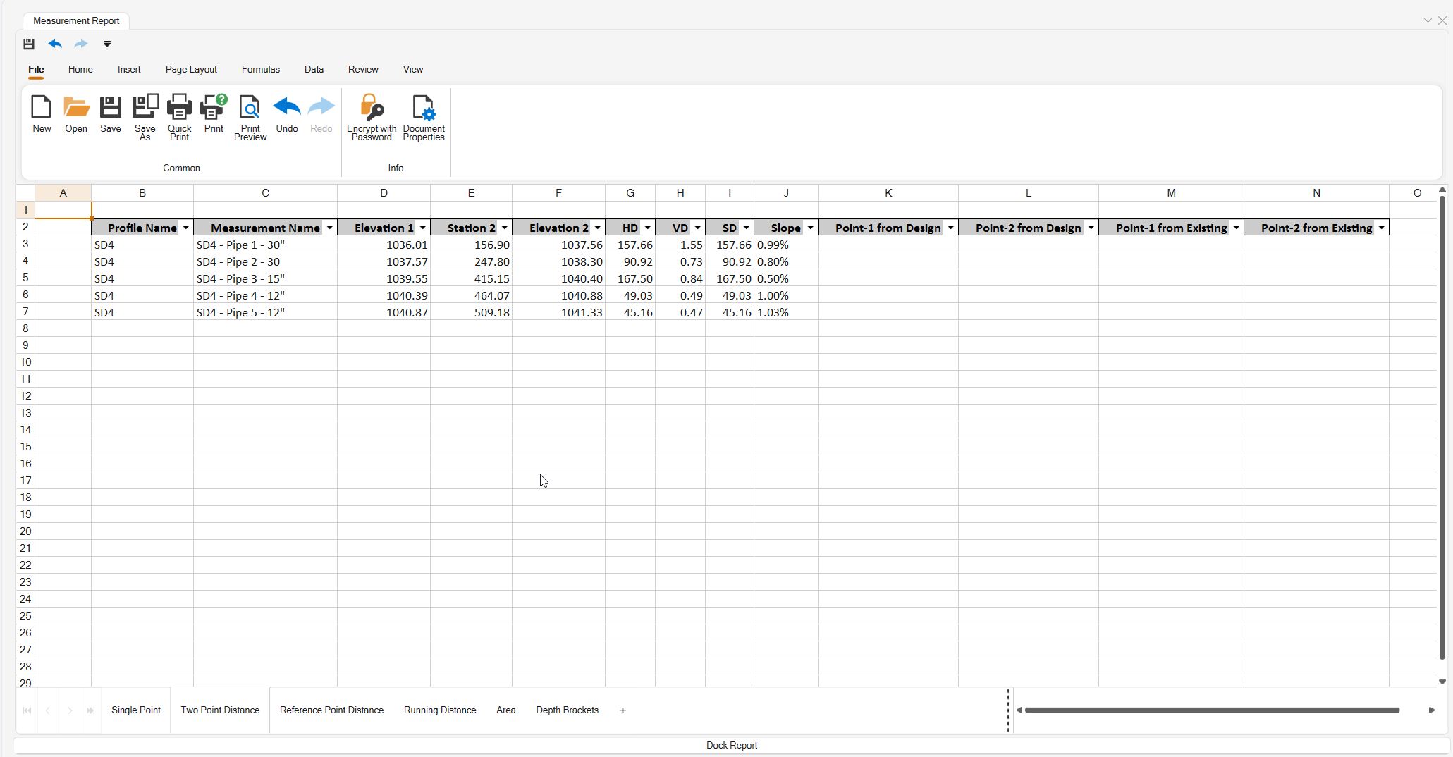
Two Point Distance Report e.g. For Pipe Lengths and Slopes
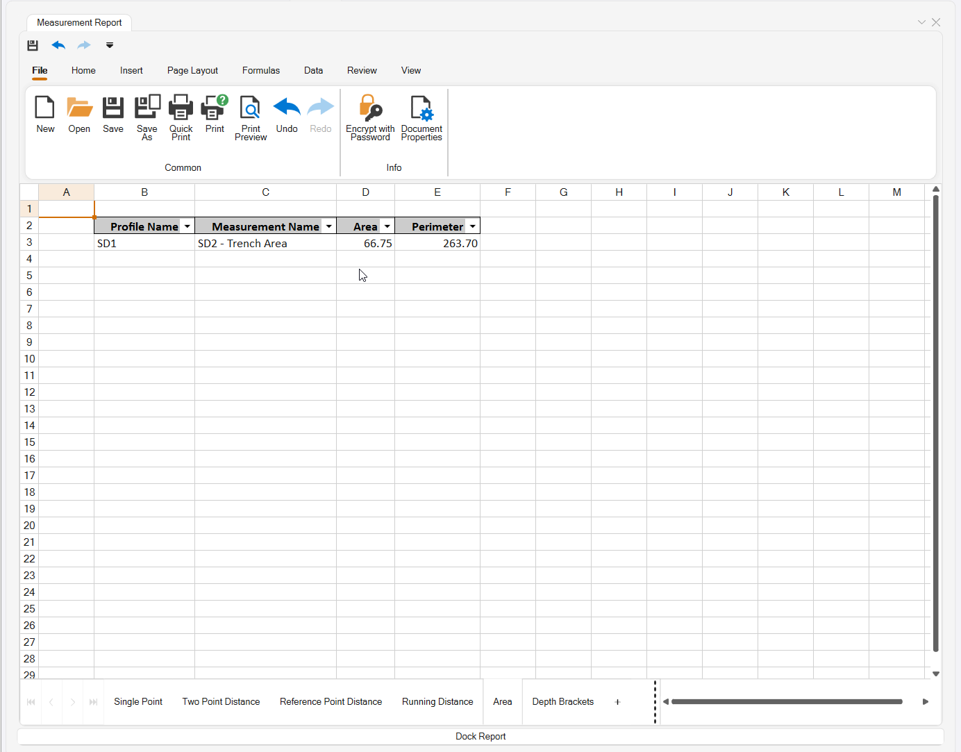
Area Report e.g. For Trench Profile Areas ) (x Trench Width = Volume)
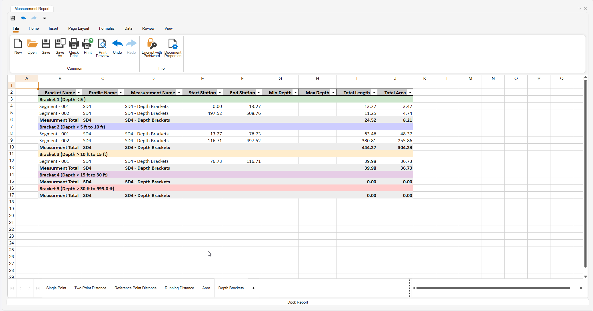
Depth Brackets Report - To Split a Run Into Depth Brackets for Costing Purposes
Other Dialog Controls
Switch Cmd button
The Switch Cmd button provides the ability to quickly switch between currently running Smart Suite commands. It also provides the ability to Close the current command or Close All commands that are currently running. You can also access the switch command list of running commands directly on your cursor by pressing the ESC key on your keyboard.
Header Bar Commands
In the header bar of the command dialog you will find icons that provide quick access to other commands that may be useful while running the Smart Profile command.
Header Bar commands include
- Command Help
- RPS Settings
- PDF Manager
- CAD Cleanup
- Smart Select
- Smart Draw
- Smart Edit
- Smart Elevate
- Smart Feature
- Smart Model
- Volumes Manager
- Smart Takeoff
- Smart Plot
- Quick Alignment
- New Profile View
- Profile Viewer
- Create Corridor
- Profile Viewer
- Reverse Line
Command Tips
The Command Tips section of the dialog contains link to the command help (this document). It also contains any tips, tricks or keyboard shortcuts that may be useful to know while running the command.
Use Case Videos
The following videos show the use of the Smart Profile command in a work process context
Feedback and Enhancement Requests
If you would like to provide feedback on the use of the Smart Profile command or to request enhancements or improvements to the command please click Reply below.