Smart Feature - Draw Features Functions

To Return To Smart Feature Command Documentation - Click Here
When we get to this point in the command, we have to decide what we are going to do to create Features. Features can be created using a number of different methods that are documented in the sections below.
Features can be created by Drawing Lines, Copying Lines, Assigning Features to Lines, by Tracking Lines and drawing methods combined, by Region Tracking a selection of Lines, or by Shrink Wrapping existing Lines.
Features once created, have attributes like Station, Phase or other, and you may want to mass edit the attributes for a selection of Features.
The Draw Features component of Smart Feature provides all of these abilities.
Draw Features Overview
The Draw Features dialog looks as follows
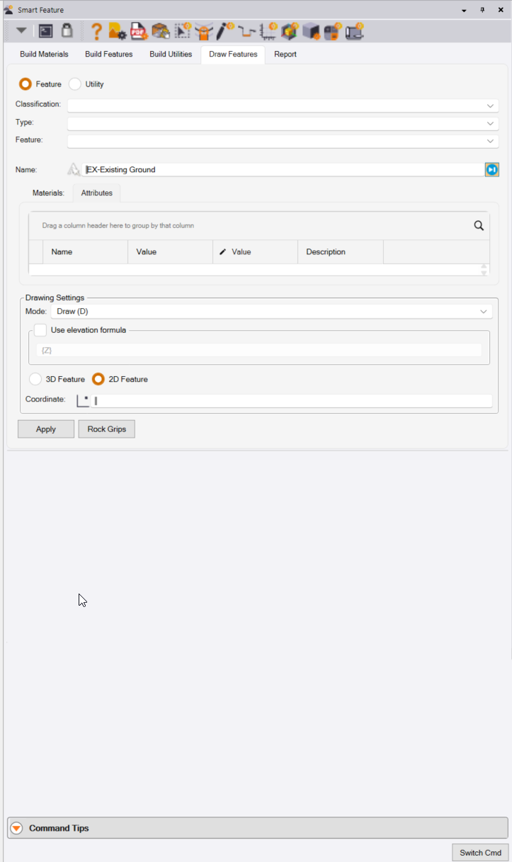
Feature or Utility Radio Buttons
Select whether you are creating a Feature or a Utility Feature by clicking the appropriate radio button.
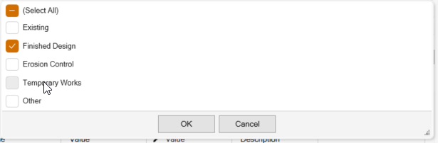
Classification
Select the Feature Classification that you want to work with. This presents a Drop Down list of Classifications, you can select one or more of the options to filter down the list of features to choose from. Check the checkboxes next to the Classifications that you wish to work with and then press OK. Click Select All if you do not wish to filter on the Feature Classifications.
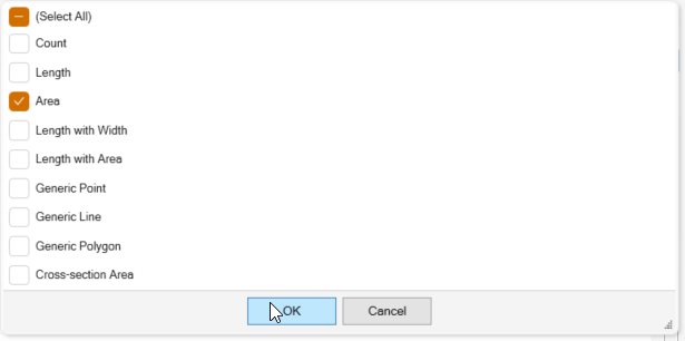
Type
Select the Type of Feature that you want to work with. This presents a Drop Down list of Feature Types, you can select one or more of the options to further filter down the list of features to choose from. Check the checkboxes next to the Feature Types that you wish to work with and then press OK. Click Select All if you do not wish to filter on the Feature Types.
Feature
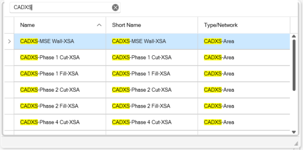
When you click in the Feature field, you will be prsented with a list of Features that match the Classiication and Feature Type filters that you have applied. Select the Feature that you want to work with. If the list is still long, you can enter a text string in the bank field at the top of the dialog which will be used to filter down the list to just those Features that contain the text string in their Name, Short Name or Type
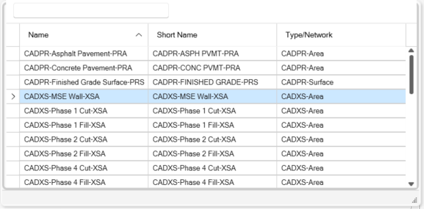
Further filtered list using CADXS as an additional filter control.
Note that if you are looking for special characters like - or + or ? or Space then you can write the filter as ‘CADXS-’
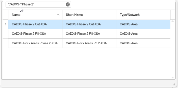
Note also that you can look for several filters at the same time e.g. ‘CADXS-’ ‘Phase 2’ will find Features that meet both criteria
You can also click in any of the column headers to sort the data in the data grid alphabetically or reverse alphabeticaly.
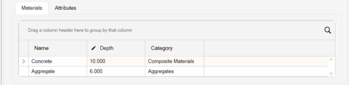
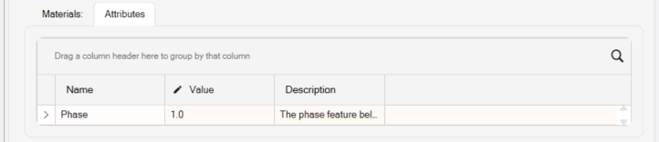
Feature Materials and Attributes
The selected Feature’s Materials and Attributes will be displayed in 2 Tabs as shown below. Select the tab that you wish to review. Note that the data displayed are the default values assigned to the Feature in its’ Feature definition. You can override the default values at this stage i.e. if the default thickness of concrete for a Building Pad is 10”, and the slab you want to create for this Building is only 8” you can change 10 to 8 at this point before creating the Feature. Note that once the Feature has been created, the Material Thicknesses will be stored as attributes for the Feature lines, you can select a line, review its properties in the Properties Pane and change the material thickness there also.
Assign (A) Mode
Assign Features to Extracted PDF or Imported CAD or Survey Data
If you have extracted PDF Vectors, imported CAD files or imported survey data you can simply assign features to the TBC objects i.e. all these polygons on this layer ae Building Pads, all the lines on this layer are Curb lines etc. You can also Auto Assign Features based on Object names matching Smart Feature Short Names i.e. if you have a Smart Feature called Building Pad that has short name BGPAD, and you import survey data that has lines that are closed that are named BGPAD, you can use the Auto Assign function to create the Smart Features directly from the Survey linework (all features processed in a single execution).
Use existing lines to create Features, for example you have 30 rectangles that were imported from CAD or extracted from a PDF file and you want to turn them all into Building Pad Features.
Hot Key
Click the A key on your keyboard to change to Assign Mode.
Copy (C) Mode
Copy Linework To Create Smart Features
In some cases, you may want to retain the source data and create a copy from which to create the Smart Features. In this case you can use the Copy mode to copy the linework and use the Copy to create the Smart Features.
Use existing lines to create Features, for example you have 30 rectangles that were imported from CAD or extracted from a PDF file and you want to turn them all into Building Pad Features, but in this case you want to keep the existing CAD pr PDF linework and make the Features using a copy of that linework. You may also be using the same line for two different purposes e.g. the line could be a surface boundary but also a Topsoil Strip area.
Video Demonstration
The following video shows you how to use the Copy (C) Mode
Hot Key
Click the C key on your keyboard to change to Copy Mode.
Draw (D) Mode
Draw / Trace Smart Features over PDF Drawings
If you have imported PDF files using PDF Manager, you can trace over those images using vector snaps to the PDF objects to ceate Smart Features i.e. Draw a Curb Line, Draw a Building Pad, Draw a Sidewak etc.
Draw or Trace the Feature e.g. You have georeferenced PDF pages visible, and you want to draw a pavement lane or building pad over the top of the PDF pages. Note that you can use the CTRL and Left Click to create an Arc in the line being drawn or repeat the CTRL and Left Click on multiple successive points to create a smooth curve. In this mode you can select 3D Feature or 2D Feature i.e. if you have a Feature that is defined as a 3D Single Elevation Feature, you can override it here to make it a 2D Feature e.g. if you are just doing a 2D Takeoff.
Click the D key on your keyboard to change to Draw Mode.
Track (T) Mode
Track Linework To Create Smart Features
In this case there is not a 1:1 relationship between the linework that you have and the Smart Feature that you want to create. The Track function allows you to use a mix of cicking coordinate locations for line nodes as well as selecting existing luinework to incorporate into the Smart Feature being created.
In this mode you wil create the Feature by a combination of Drawing lines or by Tracking existing Lines to create the Feature. For example you have a road that has a let edge of pavement and a right edge of pavement but no end of pavement or start of pavement lines. You want to create a pavement area for e.g. Asphalt Pavement by tracking the edge of pavement lines and adding in lines that connect across the start and end of the pavement area. In this mode to track a line, you can use the J = Join hot key, hover over the line that you want to add and then select the From and To location alon that line that you wish to use.
Video Demonstration
Hot Key
Click the T key on your keyboard to change to Track Mode.
Region Track (R) Mode
Region Track To Create Smart Features
In this case you want to create an Area / Polygon based Smart Feaure from a collection of lines and or polygons that define the area that you want to create. If polygons are selected, you can track a region that also includes holes e.g. to create a Toposoil Strip area that excudes internal Demolition Areas, or to create a Pond Liner Area that excludes some Concrete Sump Areas, or a Landscaping Area that excludes the Building Pads of a Subdivision.
In this mode you can track a region that follows other lines to create an area or area with holes in it (Track Interior Regions / Merge Holes. For example if you have an xisting Ground Surface Boundary and a number of Demolition Areas inside that boundary that you want to exclude from Topsoil Stripping that will be applied to the site, use this mode to Track the region between the Existing Boundary and Demolition Areas to achieve this.
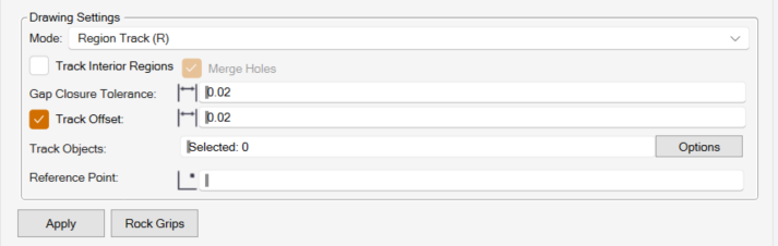
Track Interior Region Checkbox
This checkbox can be used with or without the Merge Holes checkbox. When used without the Merge Holes checkbox, the process will find an outer area and inner areas from selectd lines automatically depending on where you click the Reference Point.
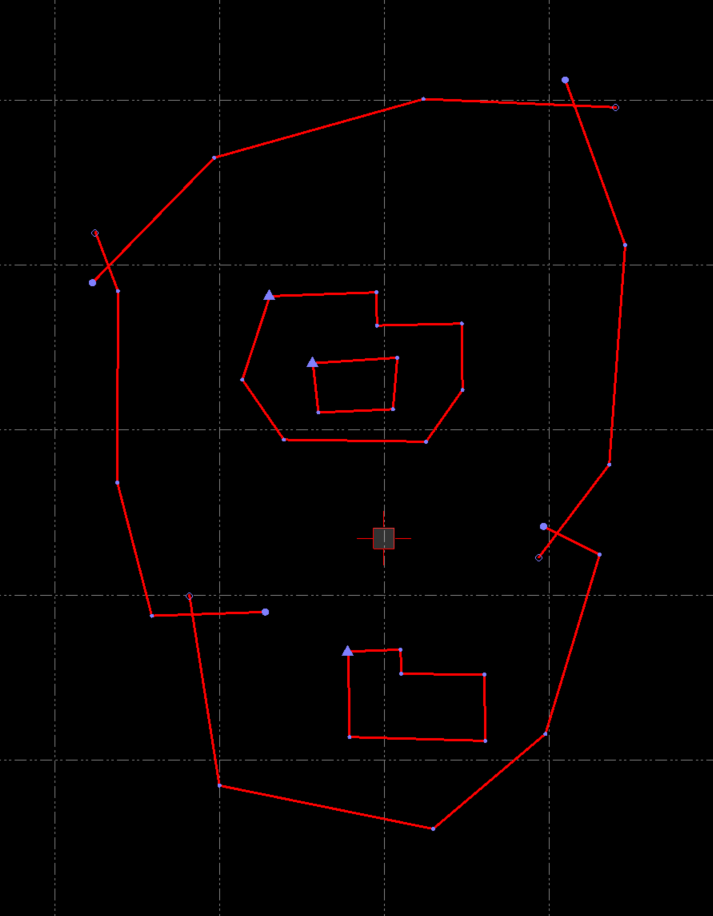
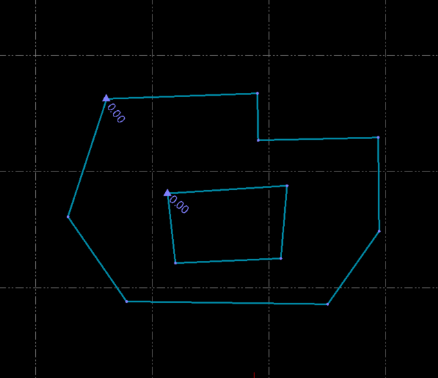
The Reference Point selected is where the cursor cross hair is shown. If I select all of the above linework and use the Track Interior Region funcion, I will get the Blue Lines in the below image.
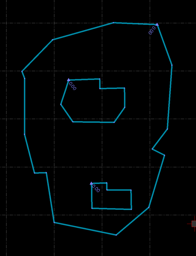
The processor looks for the first line on the outside of the cursor location and te first line(s) on the inside of the cursor position to determine the Regions to create.
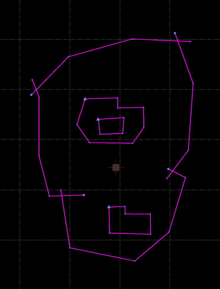
If the Reference Point was selected as shown in this image
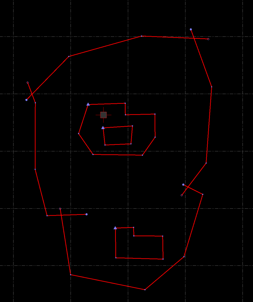
I would get the following result
Merge Holes Checkbox
In the above example, if the outer limnit region was my Topsoil Strip boundary line, and the inner areas were demolition areas, then I need to create an area that includes all of the area inside the outer region, but eliminates the areas where the demolitions are because there will be no Topsoil to strip in those areas. This is where you use the Merge Holes checkbox in combination with the Track Interior region checkbox.
In this case you would select all of the lines and select the shown cursor location as your Reference Point
And this would be the end result
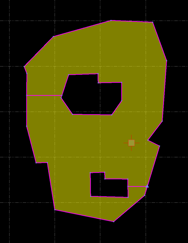
Note that the boundary line cuts in and around the two demolition areas to create a single boundary line that contains the holes in the area that we require.
While this process works to define areas like Landscaping for Finished Grade and Toposoil Strip for Existing, the lines that Cut In / Out to eliminate the Holes can ceate model challenges down stream. For this reason, any linework that is created this way is copied to a special layer in the 99D - SITE DATA Layer Group called “TO - EX-TSSTRIP-A - Region Track Lines (where EX - TSStrip-A is the short name of the feature that was created) so that when it is utilized in a surface model, it can be treated in a specific way. The copied data is placed on the layer and is made non selectable so that you do not delete it by mistake. Do not select and delete that linework if you want your final Takeoff Surfaces to be correct.
Gap Closure Tolerance
When you select a set of lines to create a Region Track, you may have small gaps that you do not notice between selected lines that would cause a region track to fail. You can set the Gap Closure Tolerance value to solve this issue. Note that while you can enter any size of value here, we do not recommend that you use a large value because that can affect how well the boundary tracks the selected lines where lines come together.
Track Offset
When checked, you can also offse the Region Track line that you will be creating. For most RPS Smart Feaure / Smart Takeoff functions you do not need to utilize this Track Offset function so leave it unchecked unless you have a specific reason to utilize it.
Track Objects
Select the objects that you want to region trac to create an Area Feature
Reference Point
Select the Reference Point location. Note tat the Referece Point can be inside the area being tracked or outside the area being tracked i.e. if you have selected lines as shown above, and you only want the outer boundary then you can click outsde the linework selected to find the Outer Boundary only.
Video Demonstration
The following video shows how to use the Region Track Mode.
Hot Key
Click the R key on your keyboard to change to Region Track Mode.
[/details]
Shrink Wrap (S) Mode
Shrink Wrap to Create Smart Features
In this case you want to create an Area based Smart Feature by tracking a boundary around selected linework that doesnt form a boundary on it’s own e.g. Existing Contours to define an Existing Ground surface model boundary.
In this mode you can create a line that tracks a region around selected objects. In this case the lines do not have to collectively form a boundary line, this process shrink wraps the objects / area based on some user entered parameters, e.g. if you have a set of Existing Contours and you want to create an Existing Surface Boundary that tracks around the contours, this woulld be the mode to choose.
Hot Key
Click the S key on your keyboard to change to Shrink Wrap Mode.