We are pleased to announce the release of v2026.2 of the RPS Command Library today - Tuesday 13th May 2026.
Installation Details
To download the latest installer package - Click Here
Note: To install the v2026.20 command library package, you must use the downloadable installation package. You will need admin rights to run the installlation package. Contact you IT department for assistance as necessary. Once installed, TMLStatus will now be usable again to keep your command library up to date for bug fixes and enhancements that we release.
Release Overview
This release is a culmination of 4 months of work following on from the Power Users Conference (PUC) in January, at which we received many requests for fixes, enhancements and new features to improve Data Prep, Takeoff and Field Operations work processes. Over 70 enhancements have been made in line with those requests in addition to our planned development activities for the period.
We continue to focus on the refinement of our multi-step work process for Data Prep and Takeoff which includes
- Command execution using the Smart Navigate command
- PDF Data Management using the PDF Manager command
- CAD / Extracted PDF Data Cleanup using the CAD Cleanup command
- Data Prep using the Smart Select, Smart Edit, Smart Draw, Smart Elevate commands
- Surface Modeling, Cut Fill Maps and Volumes using the Smart Model command
- Takeoff using the Smart Feature (2D) and Smart Takeoff (3D / Earthworks) commands
- Road and Utility Takeoff using the Smart Profile Command
- Drafting using Smart Label, Label Points, Label Lines, Label Slopes commands
- Plotting / Deliverables Creation using the Smart Plot Command
While there are many other commands that also play a role in the process depending on the details of what you are doing, and we have other commands that can be used for additional workflows (Point Clouds, Solar Farms, Reporting, Cloud Services (AI Connection), Cross Section Conversion, Curb and Gutter / Slipform Paving etc.), the above commands together provide an encompassing workflow to execute most Data Prep and Takeoff tasks.
Major focus areas for this release include
- Command start up and license check speed improvements.
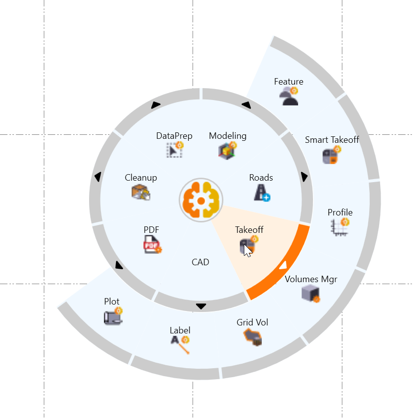
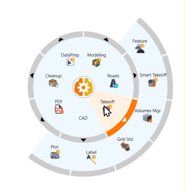
- Improve RPS Navigator to provide smoother and less sensitive control over the selection and execution of commands. The new Takeoff_MR2 Navigator Menu reflects the changes made in this release.
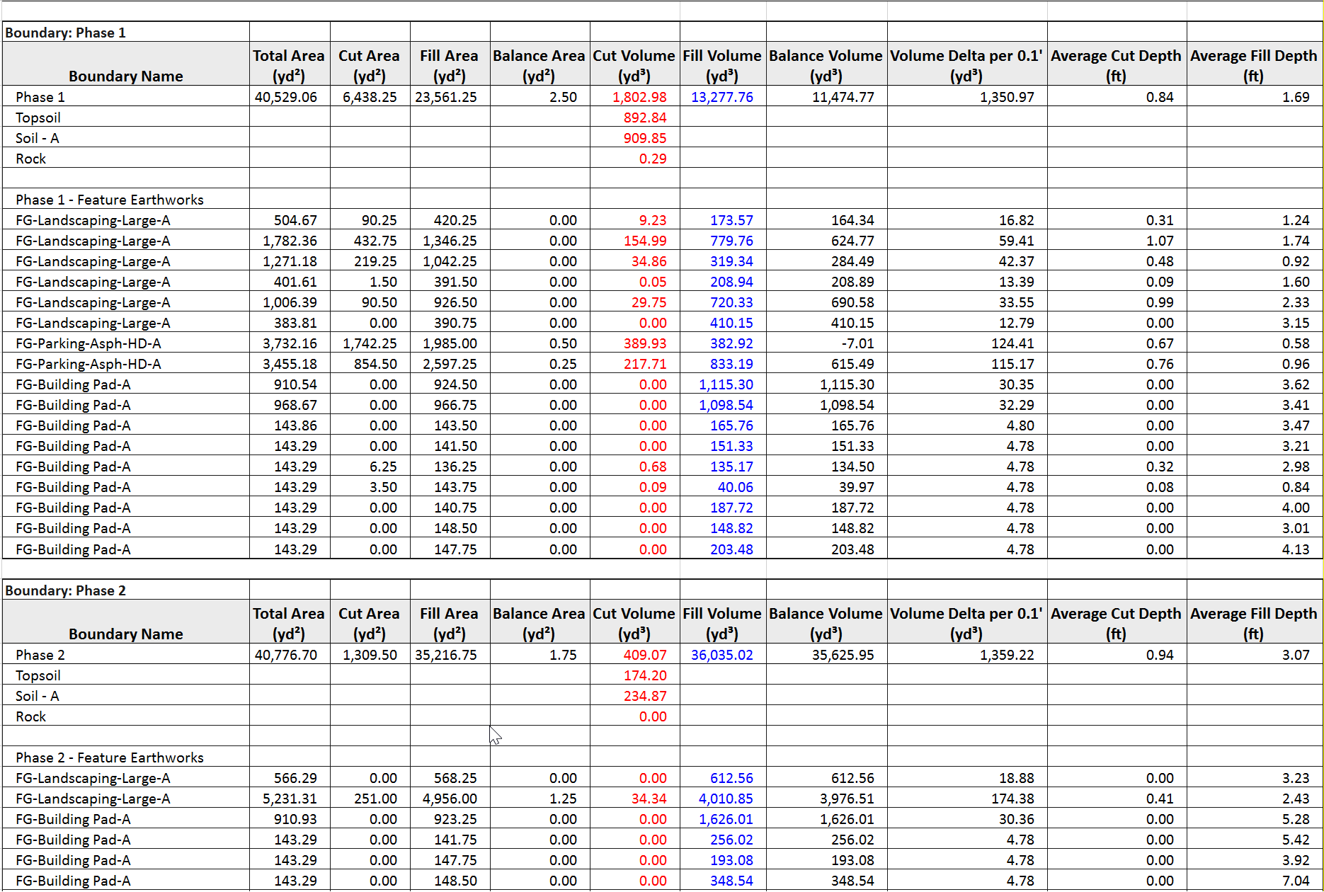
- Smart Takeoff is now fully functional. The command provides a complete 3D Earthworks Takeoff workflow, including fantastic new reports using our integrated spreadsheet tools.
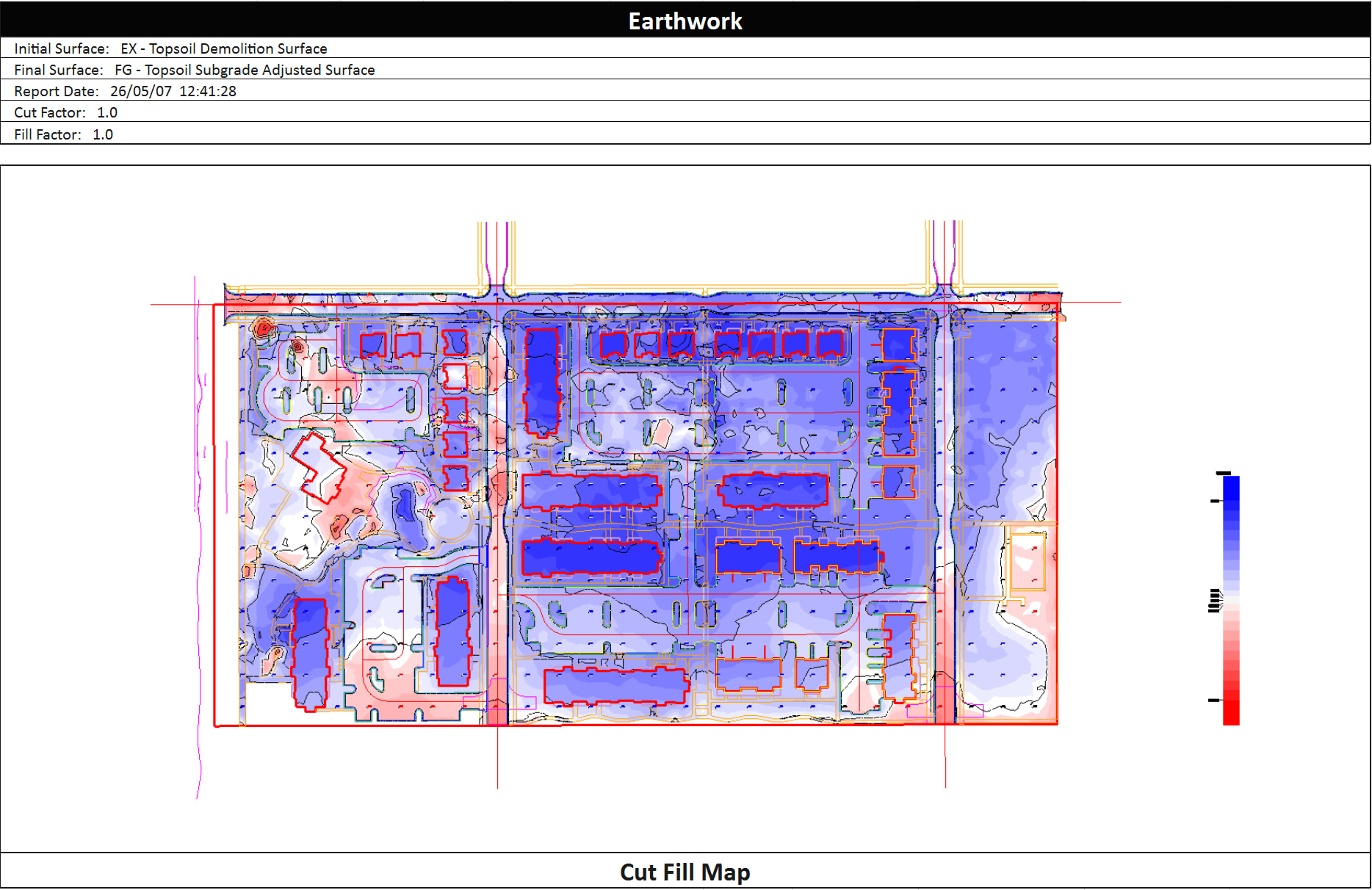
Earthworks Report - Broken Out Into Phases and Feature Sub Quantities
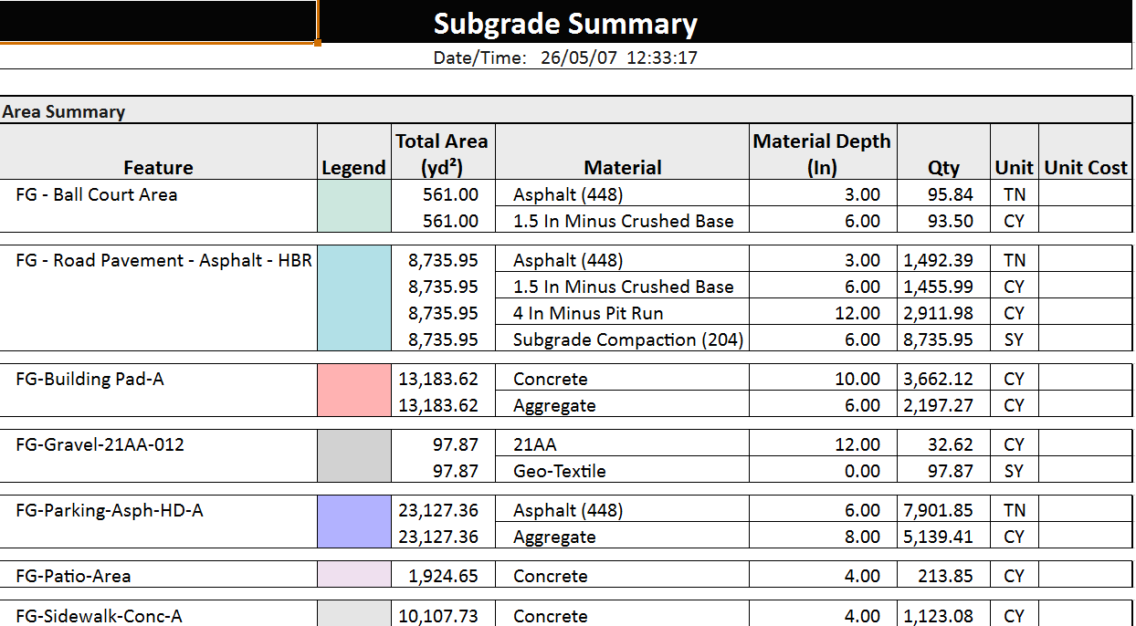
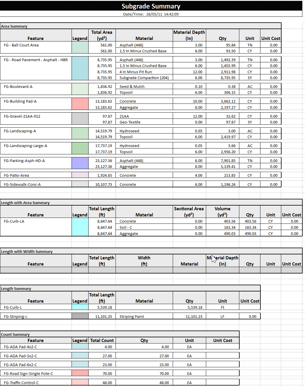
Summary Subgrade Reports
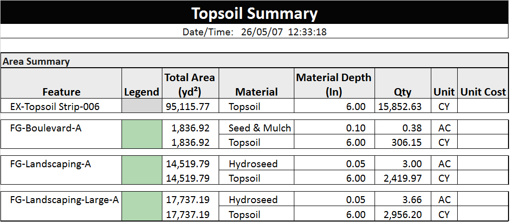
Summary Topsoil Strip and Replacement Reports
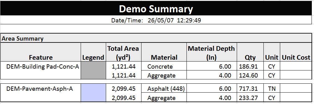
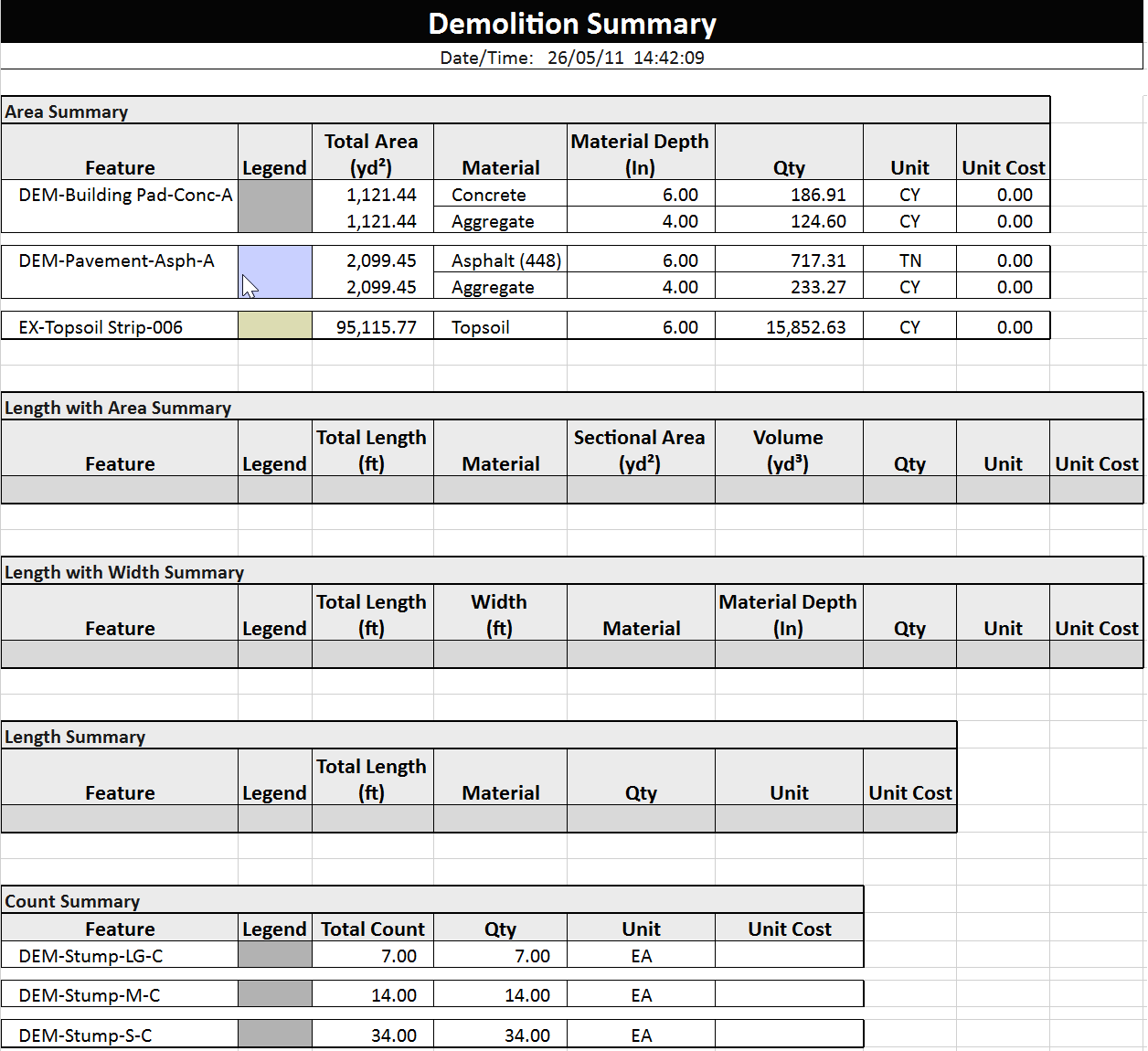
Summary Demolition Reports
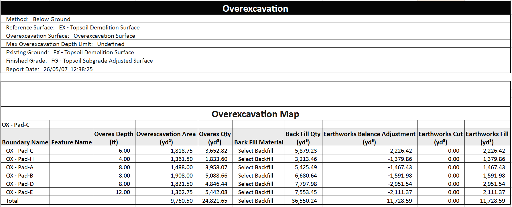
Summary Overexcavation Reports
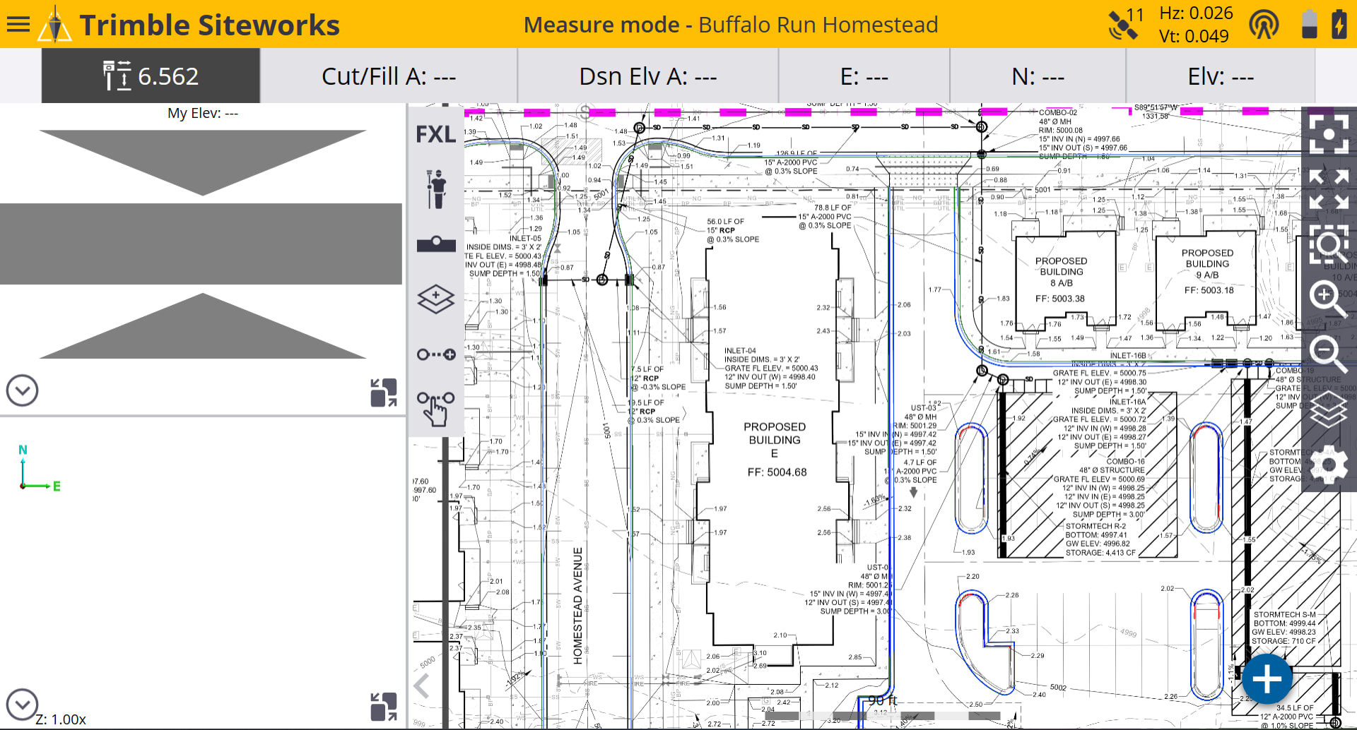
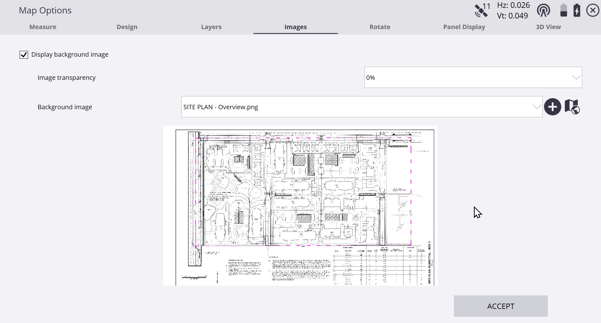
- A major update to PDF Manager. The command now provides seamless workflows to Trimble Access, Trimble Siteworks and Google Earth for all referenced images, including full support for large format roll sheets, as well as automated layout of cross section sheets for the Smart Feature Cross Section quantities workflow.
Trimble Siteworks / trimble Access Background Maps
Google Earth PDF Sheets - Automatically Generated
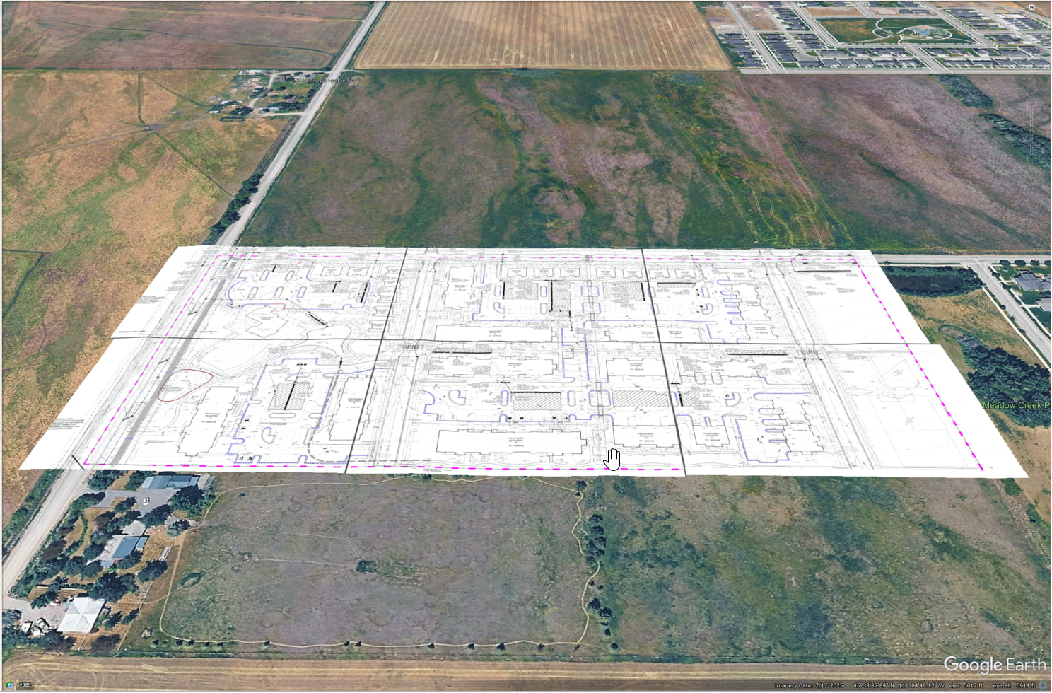
Smart Featurtes With Quantities - Auto Generated
Also Showing Google Earth 3D Objects
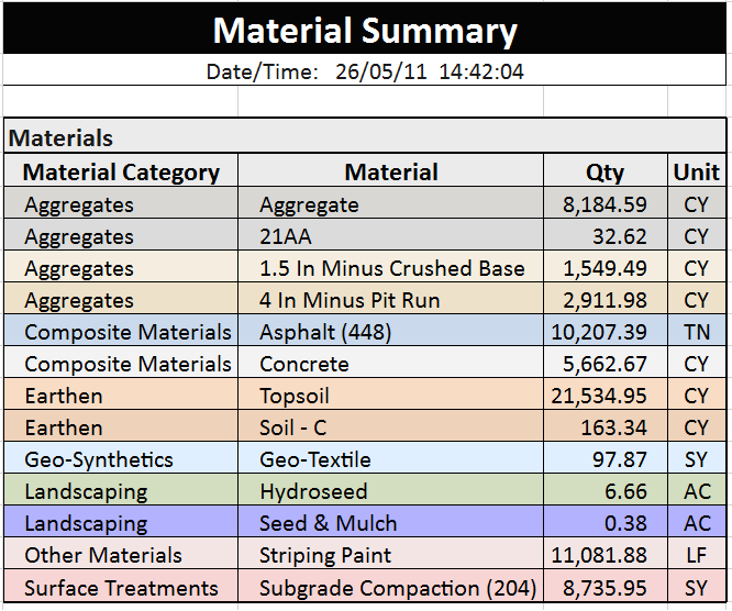
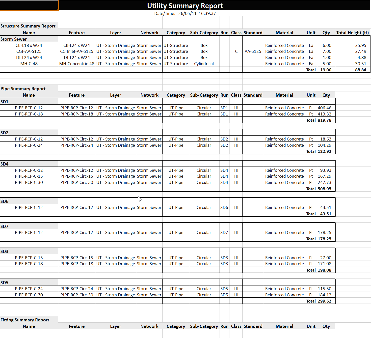
- A major update to Smart Feature for Feature based Takeoff. The command now includes a complete cross section takeoff workflow with integrated end area volume calculations for highway projects. We have also continued the evolution of the reports to now include instantly reportable summary reports for Demolition, Subgrade, Material and Utility Takeoffs.
Featurized Cross Sections
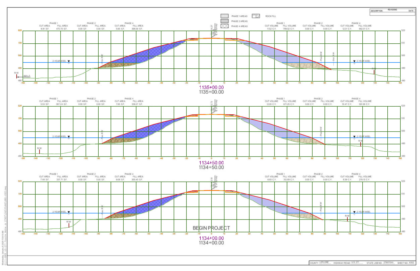
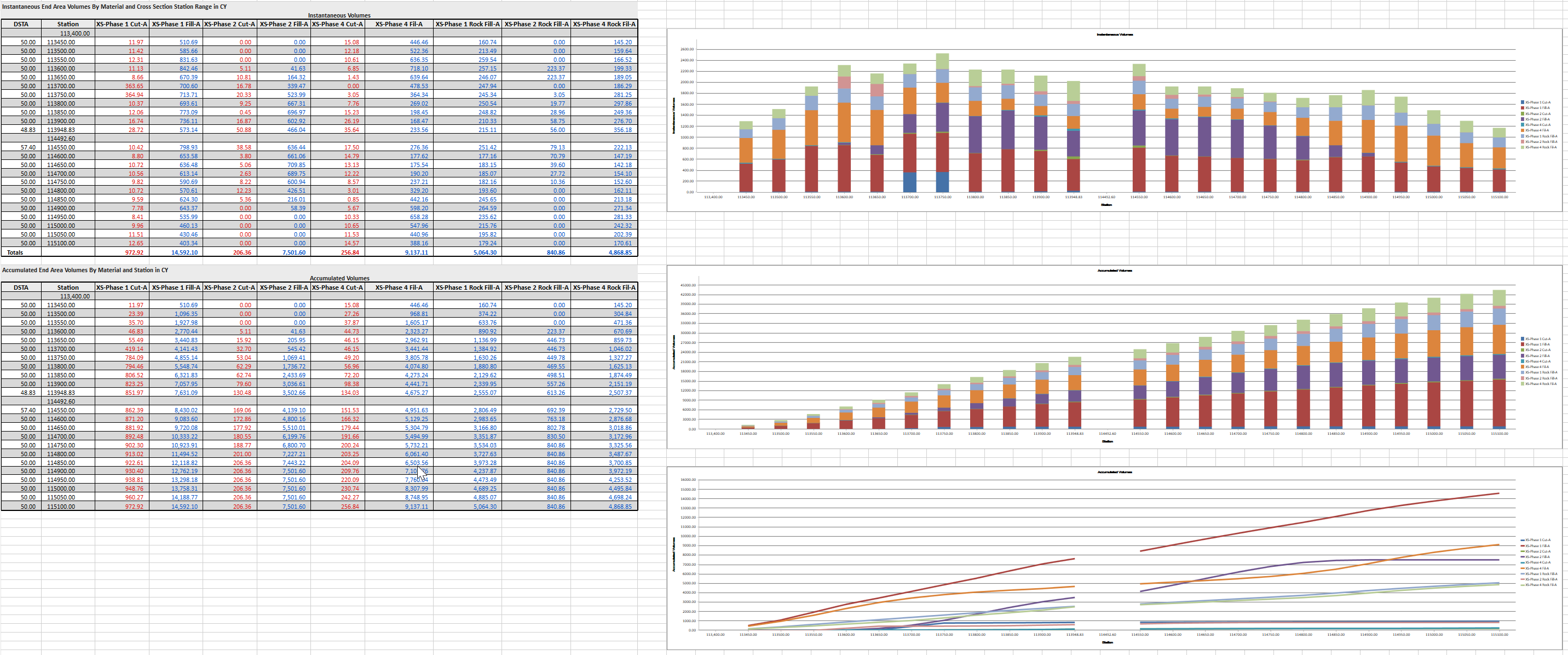
Cross Section Based Mass Haul Report with Integrated Mass Haul Charts
Demolition Summary Report
Subgrade Summary Report
Material Summary Report
Utility Summary Report - Storm Network
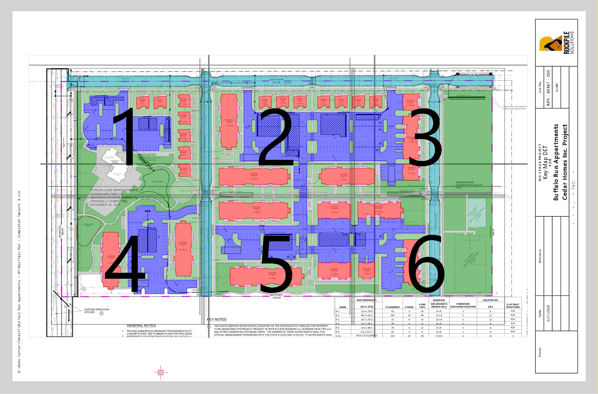
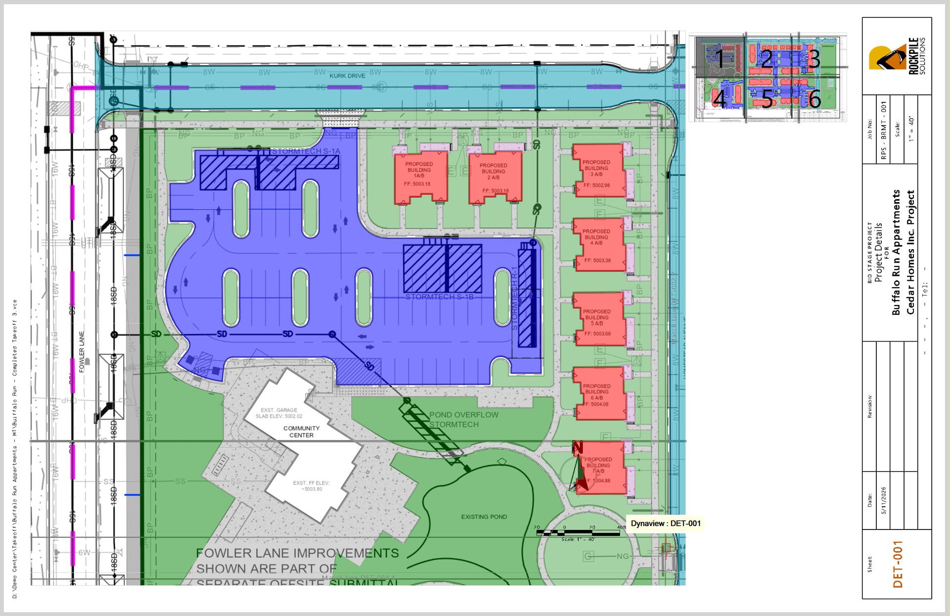
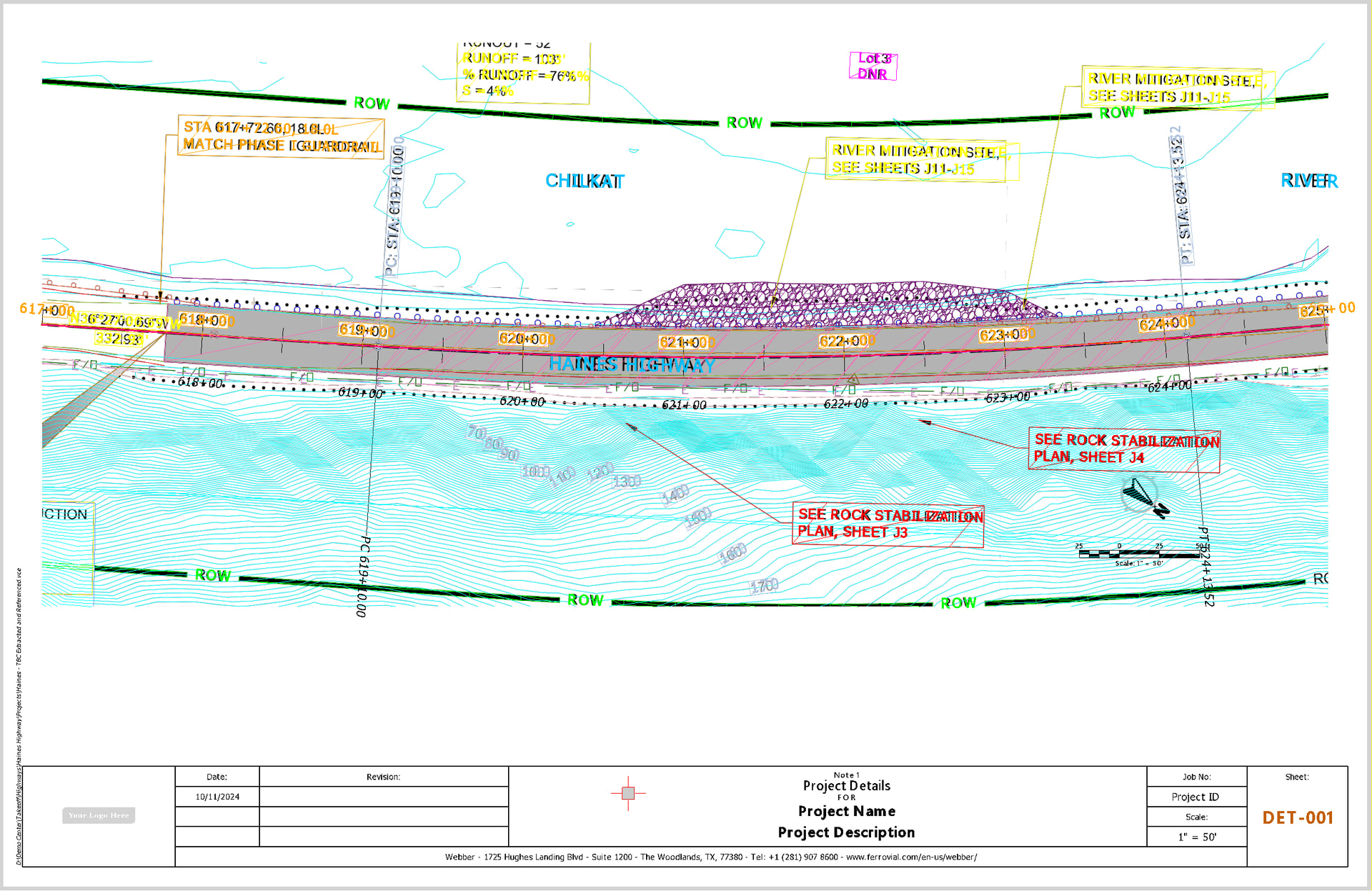
- A major update to Smart Plot for producing high quality drawing deliverables. Smart Plot now supports Grid Layout, Alignment Layout, Profile Layout, Matchlines and Key Plans as well as fast workflows for creating duplicate sheet sets.
Key Plan for Grid Layout Sheets
Individual Sheet
Alignment Based Sheets - Key Map
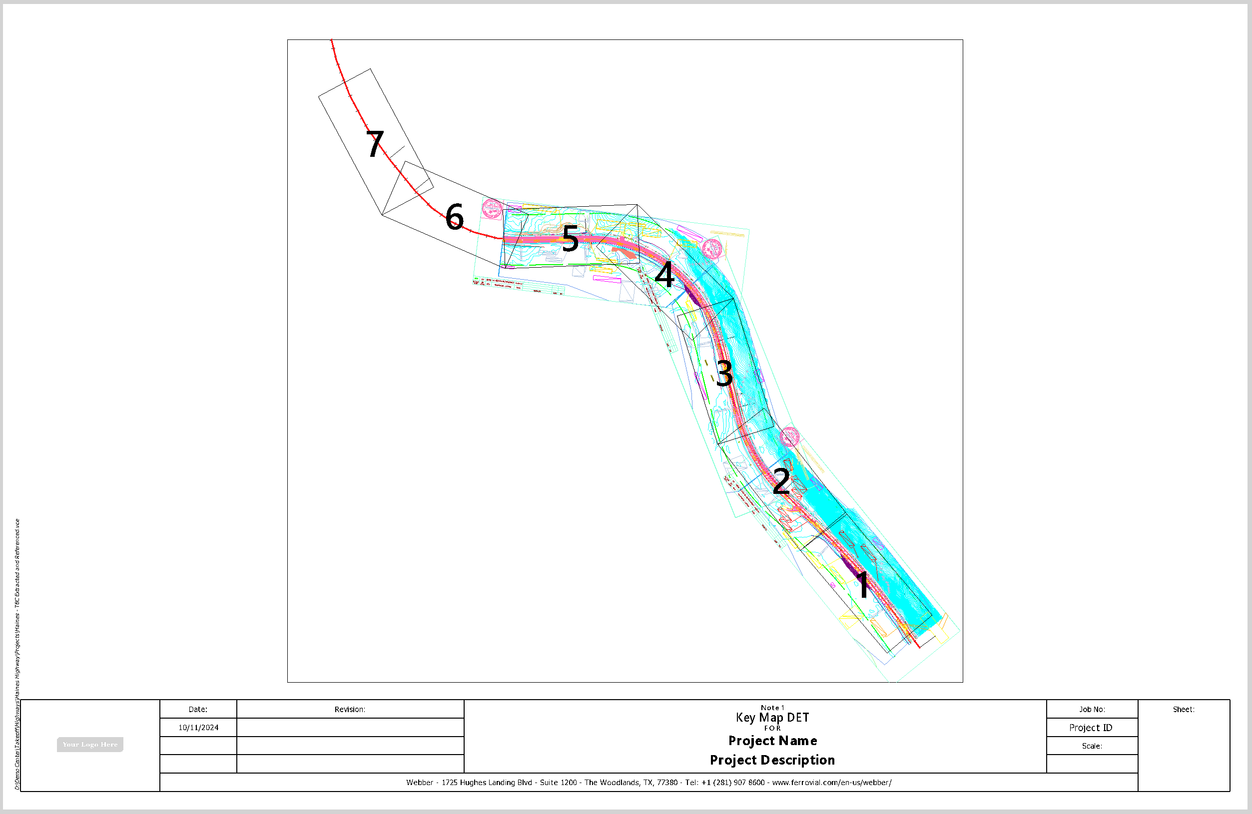
Alignment Based Sheet
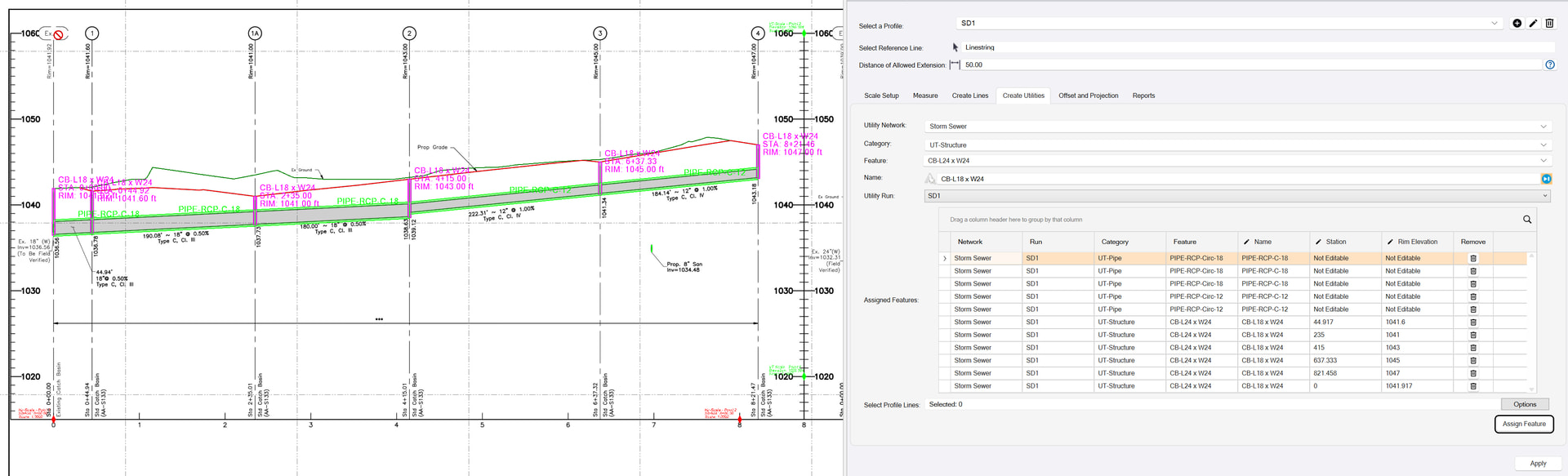
- A major update to Smart Profile. The command now supports the bidirectional conversion of data from Profile to Plan / 3D for data prep and takeoff workflows, and from Plan / 3D to Profile for As Built reporting and documentation workflows. Utility and corridor alignment workflows have also been enhanced with the ability to add vertical curves, adjust station and elevation values to accurately match the plans prior to 3D conversion, the ability to create linework and text from measurements and more.
- A major update to RPS Copy and RPS Paste. These commands now provide workflows to seamlessly move Referenced and UnReferenced images between projects.
- New Smart Label command for automated labeling using a predefined and user defined library of Smart Text labels with or without leader lines.
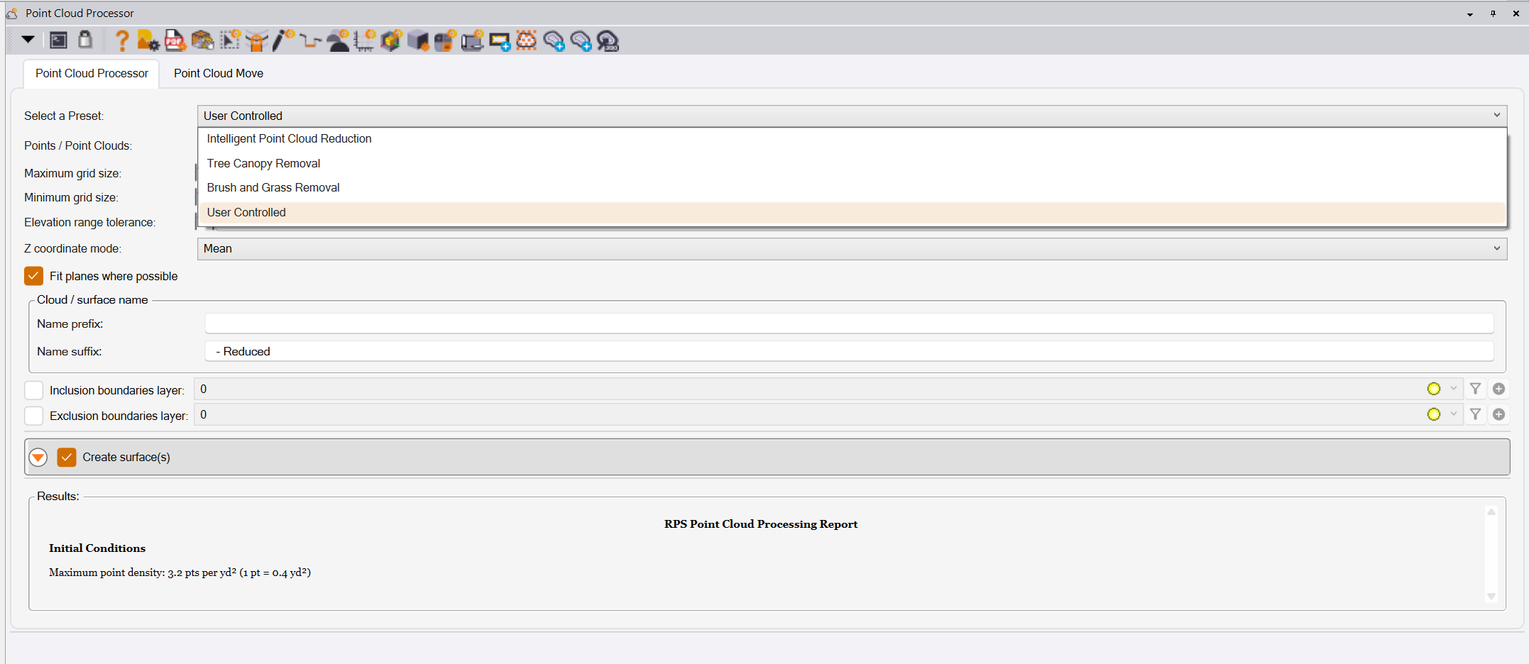
- A major update to Point Cloud Processor. The ability to Georeference a Point Cloud or Point Cloud File using any number of point pairs using least squares calculation methods has been added to the command. In addition, predefined settings options have been added to the point cloud processort to make it easier to run the command successfully in the different use case scenarios that it supports (Tree Canopy Removal, Brush and Grass Removal, Intelligent Point Cloud Reduction).
- Significant improvements have also been added to a number of other commands including Smart Model, Smart Edit, Smart Draw, Smart Elevate, Layer Manager and more (see details below for more information).
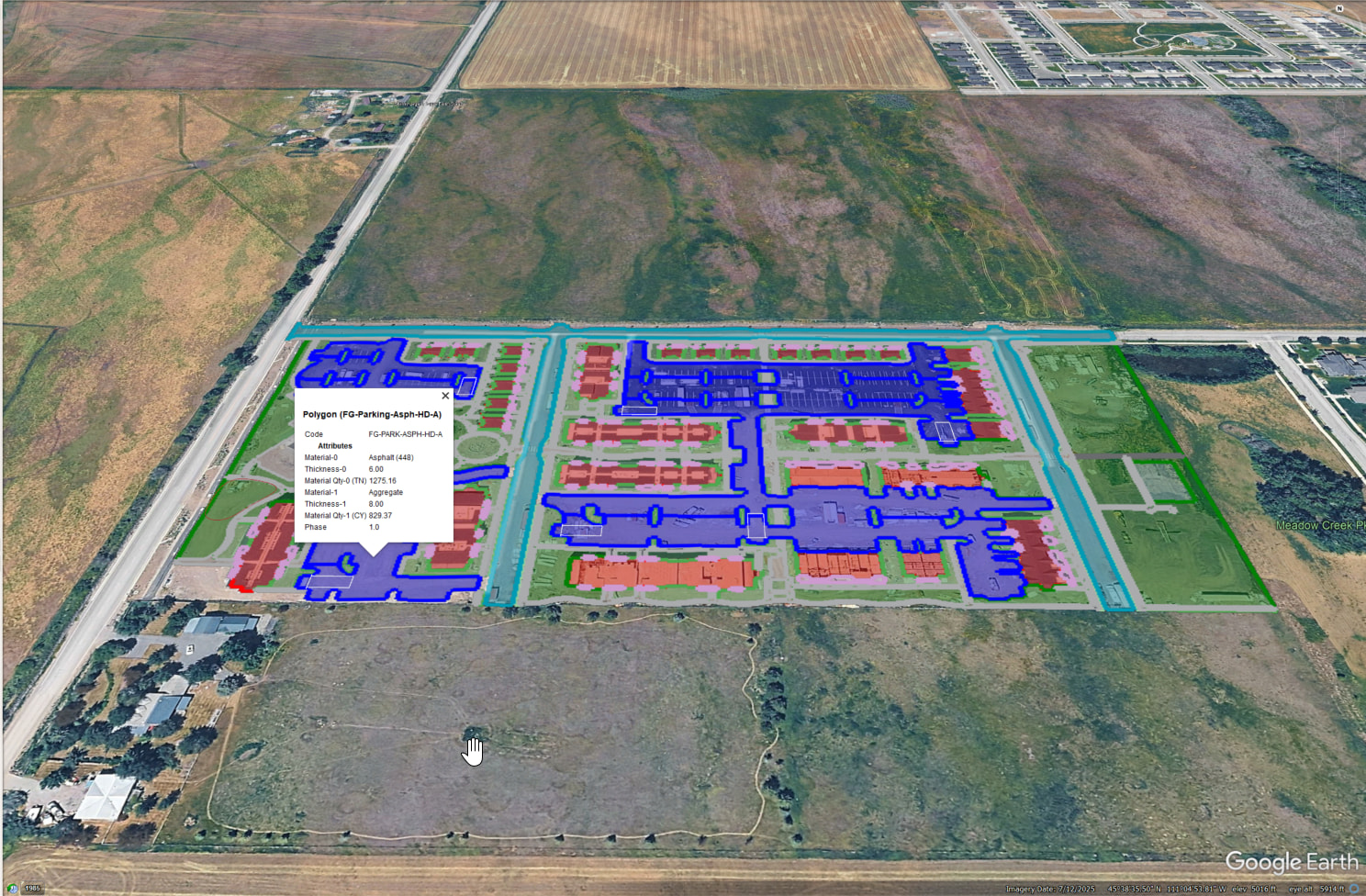
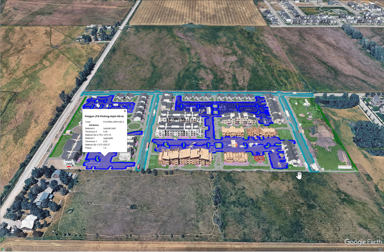
- Google Earth support for Smart Features including shaded polygons and full material quantity transfer, as well as full georeferenced image export using PDF Manager.

I have said this before, but this is the largest and most significant release I think that I have ever done in my entire career relating to software development, I am so proud of the development team and the effort that they put into the command library every day, and that it is really beginning to reach the levels that I hoped we would achieve at Rockpile when we started the company.
Release Details
Command Start Up Speed / License Checking
We have changed the way that the RPS commands check and verify licensing, and also how the commands load / are loaded to improve the speed of command startup significantly. This enhances usability amd provides smoother faster interaction between commands.
New And Significantly Enhanced Commands
The following commands are either all new or have been significantly enhanced in this release.
RPS Navigate
The navigator has been enhanced to make interaction with the commands / sub commands rings easier, so that it doesnt change command selection so easily when you move your mouse over other navigate options.
You can now drag the radial menu puck to where you want it on screen
An updated multiring Navigator menu - Takeoff_MR2 has been added to the installation package.
Smart Takeoff
The Smart Takeoff command which was initially released in December 2025 has been fleshed out in this update to now provide the following workflows.
Existing Workflows
- Build the Existing Surface using Layer Group control for selecting the data for the surface
- Build the Topsoil Strip and Demolition Surface, the subgrade adjusted surfaces have been improved significantly in this release.
- Define Strata, Boring Logs and Create Strata Surfaces. These now strongly leverage grid modeling technology to make strata computations in the earthworks report extremely fast and accurate.
Finished Grade Workflows
- Build the Finished Grade Surface using Layer Group control for selecting the data for the surface
- Build the Subgrade Adjusted Surface, the subgrade adjusted surfaces have been improved significantly in this release.
Overexcavation Workflows
Four methods for overexcavation have been created including
- Overexcavate to a depth below Existing
- Overexcavate to a Strata layer or a depth below the Strata layer
- Overexcavate to a depth below Finished Grade
- Conditional Overexcavation to both Existing and Finished Grade with ability to take the Lowest, Highest or Mean solution
Earthworks Report
The Smart Takeoff Reporting has been significantly improved using our integrated spreadsheet reporting. Improvements include
- Layout - a significant amount of effort has been put into creating compelling, easy to read and well structured reporting for Topsoil Strip / Replacement, Overexcavation, Subgrade Quantities, Earthworks Reporting.
- Colorization of cut and fill texts in the reports
- Summary reports
- Ability to add Cut / Fill Map, Site Improvement Map, Topsoil Strip / Replacement Map, Overexcavation Map to the individual reports
- Organization of the Earthworks Reports using Phases, Other Regions and Overall Totals
- Provided strong support for Cut Factor, Fill Factor and or Haul Bulkage in reporting of all earthworks quantities
Computations
The computations are all now multi threaded and optimized for maximum performance, the subgrade and overexcavation surfaces are all created using accessible linework and points, so that you can modify them as you need if necessary.
Smart Feature
The Smart Feature Command has been significantly improved from its initial December 2025 release in the following ways.
New Functions
- New Cross Section Area Takeoff and End Section Area Mass Haul reporting, complete with Mass Haul Charts automatically generated.
- Major reporting improvements in terms of look and feel, quality, detail and summary reports.
- New Drawing functions to further enhance the creation of features.
- Ability to convert an MSI library into a Smart Feature library automatically to take advantage of Materials, Site Improvements and Utility Site Improvements that you may have already defined.
Reporting
- Report refresh speed has been improved dramatically
- Report summaries are now available for all types of feature (Length, Count, Area, Length with Width, Length with Area and Cross Section Area features). The summary reports aggregate all features of the same type into a single line of the report that aggregates all of the quantities together for each material layer / quantity of the feature.
- Features are now suffixed with a unique number to aid identification of the features in the detail reports with the features in graphics.
- New Cross Section Area reporting and mass haul end section area report for all cross sectional area features, complete with mass haul charts that show instantaneous and accumulated material volumes by station for the alignment of the calculations.
Draw Features
The Draw Features part of the command has been enhanced through the ability to
- Draw 2 Point and 3 Point Rectangles to represent features
- Draw 2 Point and 3 Point Circles to represent features
- A new Edit Mode that allows you to mass edit attributes of features eg Station values for Features drawn into Cross Section sheets
- Use hotkeys X to abandon the drawing of a feature and Shift X to back up one step at a time of a feature that is being drawn
- Show Direction arrows have been added to the Assign, Copy, and Track draw processes to aid identification of Left / Right side deployment of Length with Width Features.
MSI Library Conversion
- A new MSI Library conversion tool has been added to the command that provides full support for Materials, Site Improvements and Utility Site Improvements to kick start your use of Smart Feature / Smart Takeoff workflows.
Smart Plot
The Smart Plot command that was introduced in December 2025 has been significantly enhanced in the following ways
Template Expansion
- New USFT Templates for Roll Sheets for 24” and 36” width sheets, starting at 60” length and increasing in 1 foot increments up to 120” length.
- New Metric Templates for Landscape and Portrait orientation sheets for all ISO size sheets from A0 to A4 that include a Horizontal or Vertical title block using our Traditional Style sheet layout.
Command Modes
- A new mode called “Along Line” provides automated layout for sheets along an alignment or 2D / 3D line of any kind. The sheet layout provides for overlap of the sheets, dynamic editing of the sheet layout (position and rotation), and if necessary reordering sheet sequences. The command also provides Matchline and Key Sheet Plan creation as an additional sheet in the Sheet Set. The Along Line mode also works in profile view for the creation of profile sheets for an alignment based project.
- A new mode called “Grid Layout” provides automated layout for sheets in a grid layout structure for site projects. The sheet layout provides for overlap of of the sheets, dynamic editing of the sheet layout (position and rotation), and if necessary reordering sheet sequences. The command also provides automated Matchline, Key Sheet Plan, and Key Plan on each sheet created in the Sheet Set. The grid layout mode also provides the option for automated sheet removal, that removes sheets in the grid that contain no data to be printed. Add additional Rows and Columns of sheets using hotkeys R and C to add and Shift R and Shift C to remove sheets from the layout.
- A new mode called “Duplicate” that provides the ability to make a copy of a Sheet Set that has already been laid out, and auto apply a different view filter to the duplicated sheets to create a second sheet set that shows different content.
Other Improvements
- In line with user requests we have added the ability to suppress dimming and transparency of georeferenced / unreferenced images on sheets for printing purposes while the Smart Plot command is running.
- Improved method of installing template libraries to avoiid installation problems caused by IT departments trapping the installation of template library elements.
- Fixed a defect where a Floating Sheet View was blocking command execution.
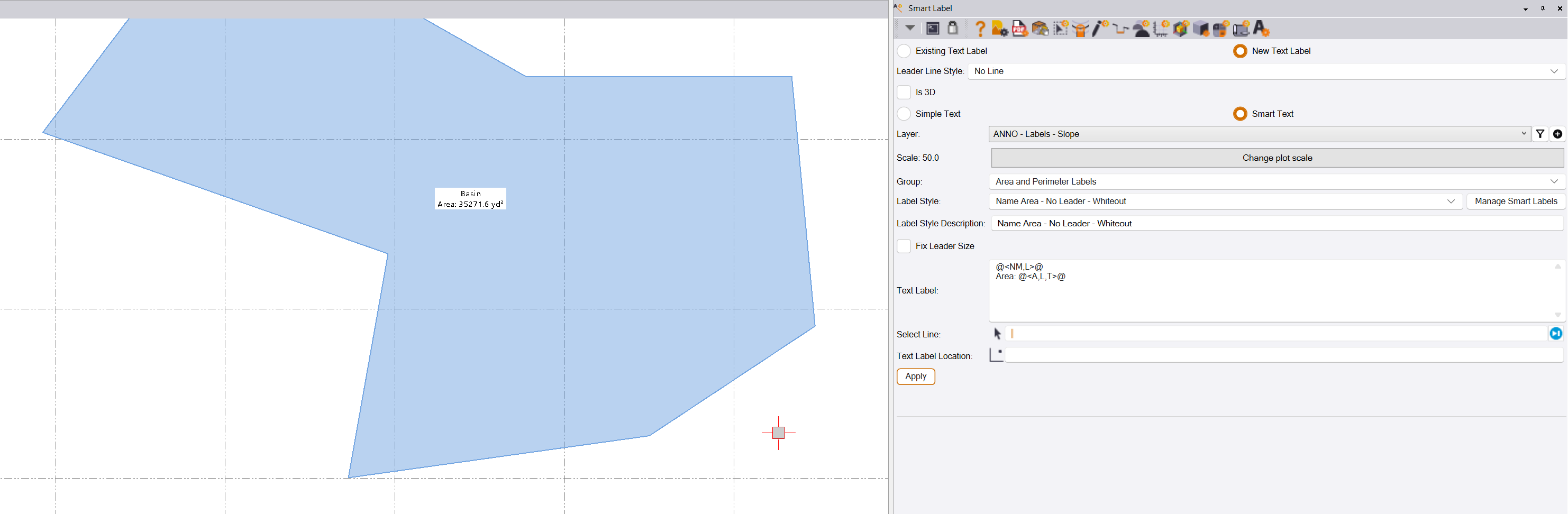
Smart Label
Smart Label is an all new command that creates labels using text or smart text, with or without leader lines. The command provides over 100 Smart Text labels in a predefined library, that can also be extended using user defined label styles. Label Styles are provided in groups to help locate the correct label quickly. The defined labels have all of the available Smart Text codes already embedded, and define how the label will be deployed including the following options.
- Text placed at centroid e.g. for areas and perimeter lengths or smart feature labeling
- Text placed along a line, in this mode the text will flow along the shape of the line following bends and curves automatically, dependent on placement location.
- With or without leader lines - leaders can be striaght or splined, and can have an optional arrow head.
- 2D or 3D placement of the text and leader lines.
- Leader lines can be fixed or variable. A fixed leader line is defined on the first label execution, all subsequent leaders will have the same geometry as the first leader, and can be placed uaing a single click.
- Whiteout for the text of the label can be selected, ideal for labeling shaded polygon areas and smart features.
- Text height can be increased and decreased using the up and down arrow keys when the command is in the text location field control.
- Text can be rotated clockwise using the right arrow key and counter clockwise using the left arrow key when the command is in the text location field control..
- Text can be aligned to a line or line segment using the CTRL key when you hover the cursor over the line that you want to align to. If you hover over the left or right side of the line, this will determine the text orientation in relation to the line (180 degree rotations).
- Text can be aligned perpendicular to a line or line segment using the SHIFT key when you hover the cursor over the line that you want to align to. If you hover over the left or right side of the line, this will determine the text orientation in relation to the line (180 degree rotations).
- Label can be set to Autoflip, so that text is always readable when a line rotates over the vertical (0 orientation) direction.
- You can also use the command to create simple text or text blocks for reuse on different projects.
- You can also use the command to add leader lines to existing text objects. Two modes are provided, one that creates a leader from a location to the text location. The other mode moves the text from its current location to a new location, and draws a leader between the original and final location of the moved text item.
- A default text height is defined for each label, along with a default text font. Text styles for use with Smart Label are created automatically by the command to eliminate the need for these to be predefined in your project template.
- Smart Label styles can be defined in a spreadsheet and loaded automatically via the RPS Settings - Smart Label Settings process. Creating a lot of smart label styles is quicker and easier using the spreadsheet method because you can copy and paste existing labels or parts of existing labels and rework as needed.
- Smart Label works in Plan, Profile, Sheet and Station Offset Views.
Smart Profile
The Smart Profile command continues to evolve as a power tool for Data Prep and Takeoff workflows. In this update we have added the following capabilities
- Support for Track and Track Region options in the measurement modes to aid tracing out areas for the calculations
- All measurements for locations, lengths, areas can now be created as linework and text on the drawing that can be printed or converted into 3D linework using the create lines option.
- In the Create Lines workflow, you can now add vertical curves into lines prior to flipping the line as a vertical alignmemnt for an alignment. You can also correct station and elevation values for any location in a profile prior to flipping to 3D, ensuring the highest accuracy results.
- In the Create Utilities workflow, you can now correct the station and elevation of strucrtures prior to flipping to 3D, ensuring the highest accuracy results
New Offset and Projection Mode
The new offset and projection mode provides the following additional capabilities to the command
- Offset Profile Lines. This mode provides the ability to create lines at offsets to profile lines, that are auto adjusted for the vertical exaggeration of the profile drawing.
- Project 3D lines and points from the Plan / 3D views to the profile drawing for the purposes of As Built documentation deliverables. This allows you to overlay your AsBuilt survey data directly on the engineers profile drawing for printing using Smart Plot. Note that points carry Description 1 (Point Name) and Description 2 (Original Point Elevation) attributes that carry the original point detail information, so that they can be automatically labeled using the Smart Label command.
- Project Surface onto Profile. This function provides the ability to create a slice through selected surfaces along the profiles reference line, and project those up into the profile drawing.
Smart Draw
The Smart Draw command has been extended to handle more drawing modes for new linework, and to further enhance the curve elements of lines as follows
- You can now use a single CTRL click on the second point of an arc to create a Tangent In arc (non tangential out).
- You can now use CTRL click on the second point of an arc and a second CTRL click on the next point to create a Tangent Tangent arc.
- You can now use CTRL click on multiple sequential nodes to create a smooth curve between the clicked nodes.
- This also means that you can now more easily draw non tangent arc ends without the need for short straight segments prior to the non tangent corner.
- You can now draw 2 Point and 3 Point Rectangles in 2D or 3D
- You can now draw 2 Point and 3 Point Circles in 2D or 3D
- You can now use Track Region directly in the Smart Draw command to create polygonal areas, with or without offsets, with or without holes.
- You can now use Shrink Wrap directly in the Smart Draw command to create polygonal areas around selected objects of the model.
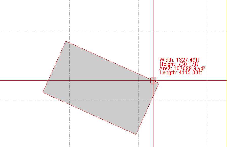
- We added on cursor text that provides bearing, distance, length, running length and distance from prior node dynamically while drawing. When drawing rectangles and circles we display the width, height and area of rectangles and radius, area and perimeter of the circle.
- We added hotkey controls to undo a step (SHIFT X) or abandon the line draw (X) while drawing lines of any type.
- Expanded Smart Draw capabilities so that it now works fully in Plan, Profile, 3D, Sheet and Station Offset Views.
- Improved node creation for closed and autoclosed lines for easier edits.
Smart Elevate
The Smart Elevate command has been enhanced as follows
- The Z formula function (and this applies to all commands that use the Z formula function including Smart Draw, Smart Edit and others), has been enhanced to better handle different elevating scenarios. The Z formula can now be written as follows
| Z Formula Examples | Description |
|---|---|
| {Z}+4000Z | Adds 4000 to the entered value. The 4000Z also controls that if a 3D object is used to derive the elevation, or if a text item is clicked to derive the elevation, that if those derived values are already in the 4000 range, the Z part of the formula will not be applied again. This resolves the incremental effect that we experienced in the past. |
| {Z}+4000Z-5DZ | Same as above, but in this case the DZ value will be applied also to the entered or derived elevation value. i.e. if you enter 26.5 then this would result in an elevation of 4021.5. The DZ part of the formula is always applied when present in the formula. |
| {Z}+2% or {Z}-2% | This can be used e.g. to elevate the edge of pavement line from the road centerline or an edge of sidewalk from the back of curb line, where you know the cross slope, and the distance can be derived from the click locations. This provides the ability to transfer elevation at a cross slope where needed. |
- A new Elevate Text By Text mode has been added. This mode elevates the text object to the elevation defined by the text e.g. a contour label for a contour elevated to 100, can be elevated to the elevation defined by the text object. This allows you to bring elevation labels and contour labels up to their absolute elevation values.
- Simple mode - Absolute, Delta, Undefined will now all elevate leader lines without converting the leader lines into linestrings.
- Elevate lines by Intersecting Line has been improved to eliminate creation of duplicate or near duplicate nodes at the intersection point.
- Some imp[rovements to highlight controls when using the command.
Smart Edit
The Smart Edit Command continues to evolve and handle more editing scenarios as follows
- New Simple Mode in Break, Join, and Trim / Extend sub modes. The simple mode provides a dumbed down version of the command for the benefit of new users, allowing them to use the Break and Multibreak, Single and Multiple join, and simple Trim / Extend functionality without the overhead of the settings required for the advanced modes.
- Ability to convert tangent arcs to normal arcs in linestring edit mode
- Ability to edit the radius of an arc using linestring edit mode
- When joining lines, we have added a right click preview function for the lines that are about to be joined. Select the first line segment as your seed segment, you can see its end point, right click on the next segment, if there is more than one line segment below the selected location, they will be displayed in a list for you, along with the distance of node 1 from the end of the previous segment end point. You can hover over any item in the list to preview where the line starts and ends. You can select a line that you want to add (that has a 0 offset), or you can delete lines that you don’t think you will need.
- Inside Smart Edit, there is now a Right Click Menu that accesses the other modes of the Smart Edit command, this allows you to jump even faster between modes of Smart Edit.
- We continue to improve the editing of 3D lines and the use of highlights in the command
PDF Manager
PDF Manager power tools continue to grow with this release. New functions include
- Full support of large format roll sheet plots
- Export of all georeferenced images to a Background Images folder in the project file for use in Trimble Siteworks and Trimble Access. all images are exported with world sidecar files. All images are sized automatically for Siteworks limits. If images are too large, the images will be first downsized in terms of resolution e.g. from 600 DPI to 100 DPI, and if still too large will be tiled into smaller images.
- Export of all images to Google Earth. A KMZ file is created in the same process as that used for Siteworks images, and the KMZ file contains all of the images in their real world locations for use in Google Earth. The KMZ file is stored in the Background Images sub foldfer of the TBC Project Folder. Simp;ly double click the KMZ file to open the images in Google Earth Pro (desktop), or upload to Google Drive for use inside Google Earth (web / cloud version)
- Exporting images also allows images to be exported in their clipped or unclipped state.
- When using a rectangular clipping boundary, you can elect to create additional nodes in the clipping rectangle. This adds an additional node in the middle of each side of the rectangle, that can help you to modify the clipping boundary prior to extracting linework from the PDF files.
- Image clipping boundaries are now created on separate layers for each page collection. This allows you to separate the image boundaries for each page collection for easier and faster editing.
- Image naming processes are now more flexible, you can also override image name when you are georeferencing the images.
- Image Clipping On / Off - you can now turn image clipping On / Off in the update georeference tab of the command. This allows you to see the full sheet details if required at any point after the images have been georeferenced.
- New Group Reference mode for laying out a large number of individual sheets quickly. This is is ideal for e.g. laying out cross section sheets in the plan view, ready for use with Smart Feature for the cross section takeoff workflow. If the cross sections happen to be rotated, this mode also allows you to unrotate the cross section sheets to make them usable with Smart Feature.
- Data Extraction now allows you to extract Lines or Text or Fills in any combination. These determine whether or not the objects will be extracted or not. The extracted objects can then be layered or relayered according to the enhanced data extraction methods.
- Data Extraction now allows you to separate data that you know you want from data that you dont think you need. All data is still extracted, but it is much cleaner and faster to work with as a result.
- Images placed can be given a View priority - 1 is highest and 5 is lowest view priority. This allows you to control the order of sheet viewing priority when the sheets lie on top of each other.
- All sheets are given a full sheet clip boundary if a clip boundary is not defined. If a sheet is given a clip boundary, it also has a full sheet clip boundary as well.
- When drawing the clipping boundary you can now use hotkey SHIFT X to undo the last node and hotkey X to start over with a new clipping boundary.
- When you are directing extracted data to specific layers, you can now set the color to ByLayer to control the color of the extracted linework.
- Improved handling of Bookmarks
RPS Copy / RPS Paste
The RPS Copy to Clipboard and RPS Paste commands have been improved to provide a seamless workflow for copying images and georeferenced images between projects. Because the images are “referenced into the project” the project file does not contain the images, they are stored in the Project folder for the project. In this new option, the Copy / Psste workflow makes a copy of all the necessary files in the target projects folder as it adds the references into the project file.
Note a TBC bug has been identified that causes Snaps to stop working when any VCL Export / Import is executed. We are told that this has been addressed in the next TBC update. If you lose your snap modes after doing a set of Copy and Paste functions, save the project, close TBC and restart the project to re-enable you snaps.
Smart Pane
The new Smart Pane command introduced in December, now supports the following workflows
- You can now import selected project objects into Smart Pane. When used with Smart Feature, this means that you can select all of your features and open them in Smart Pane allowing you to preview them in the context of a global map / satellite image / street map. Once in Smart Map you can query the quantities stored in the attributes of the features. You can also export the data from Smart Pane in a KML file for use in Google Earth.
Smart Model
The following enhancements have been made to Smart Model
- Increased awareness and handling of active views, active view view filters for improved performance. Also now handles the All Filter in a better way.
- Tree View edits have been improved significantly, allowing you to manipulate all surfaces on large projects into the correct surface groups.
- In the Cut Fill Map process we have added color coded Cut and Fill volumes by color band into the cut fill map reports.
- A Hide All surfaces function has been added to the right click functions in the tree view
- Load times when large numbers of surfaces are in play have been significantly improved.
- Select surface members has been added to the right click menu when a surface is selected
- Improved the way that Surface Classifications are being used in Smart Model volume calculations
- Surface Style defaults have been updated to better match the updated RPS Takeoff workflows. If you had custom surface styles, they will be unaffected as they are in your “custom settings” file for Smart Model.
- Layer Group surface creation methods and controls have been improved in line with the improvements to Smart Takeoff.
- In tree view, it is now easier to group select / deselect surfaces for reassignment to different surface groups using CTRL and SHIFT selection controls.
Point Cloud Processor
The Point cloud Processor command has been improved as follows
- In Point Cloud processor mode, we have added some default settings for the most common work processes, those being point cloud intelligent reduction, and point cloud tree / vegetation removal. This makes it easier for new users to get the settings right first time.
- A new Georeference Point Cloud mode has been added to the command allowing to you to move and rotate a point cloud from one location to another. The transformation parameters are computed using least squares with full residual analysis. The process can be applied to one or more scans / point cloud regions inside the project or to an external point cloud file prior to import.
Layer Manager
Layer Manager continues to evolve in this release with the following improvements
- Load times on projects with large numbers of layers has been improved drastically
- Now has the ability to create a new Layer Group
- When layers are selected for deletion, if they contain data, the data can be deleted or sent to the RPS Object Bin (this is a recycle bin), allowing you to still access the “deleted data” after the fact if needed.
- We have added a # of Objects column, so that you can see which layers have / do not have data on them.
Cloud Services
Cloud Services continues to evolve. In this release we have added
- A new user interface for the Question / Response dialogs in Ask Rocky
- The ability to save chats for later recall and reuse
- Started to add a set of QA Reports as new commands
Enhanced Commands
In addition to all of the above major changes and improvements, many other commands have been modified to varying degrees in line with user feedback requests from the Power Users Conference (PUC). Here are some of the highlights.
Volumes Manager
Numerous user interface improvements and the ability to edit existing groups that have already been defined in the command. The sequence of surfaces defined in the progress volume calculations has been protected against sorting using the table header filter and sort functions.
Create XLINES
The command has been improved in the following ways
- Each XLINE can be given a unique name
- Each XLINE can be given length Left / Right overrides to the defaults defined
- Now remembers the last used layer from prior execution
CAD Cleanup
When blocks are exploded, the data lines that are created are now added to the source blocks DXF / DWG file selection set.
- Layer removals has been improved.
- Can now set a range of elevations to undefined, allowing some elevated data to be preserved, while resetting all other data to undefined elevation.
Grid Volume By Boundary
The following improvements have been made to the command
- The cell ID has been added to the label for each cell, providing direct correlation with the reported cell IDs in the output spreadsheet.
- Connected the Cut Fill Map Interval to the Grid Cell sizing and allow overide when needed.
- Corrected the cut fill balance reporting to align with Smart Model, Smart Takeoff and Smart Feature conventions.
- Added Surface Classification support into all Grid Volume Calculations.
Rotate Plan View
Added the ability to define a Non North direction as the direction for all resets. This allows you to rotate sheets / data to a non North angle for ease of working, and then set that angle as the default for all resets going forwards.
Create Slope Indicators
-
The spacings between the indicators are now being set correctly when you restart the command.
-
When you start the command in Single Mode the snapping has been improved.
Smart Point Manager
When using Right Click COGO snaps in TBC with the command, the Northing and Easting fields were not getting populated at the same time. This has now been addressed.
Smart Stakeout
We have added a default Point Creator Style for use with Smart Stakeout that sets most of the settings required. This is now selected automatically when using the command.
- A new data entry for Distance To Box Side has been added
- The offset distance has been added into the the options for naming of the stakeout points so that field crews can see the offset distance in the point names
Smart Select
A minor defect in the Cross Section creation has been addressed
Point Creator
Default Point Creator Styles for Offset Lines and Sideslope Lines have been added to the Command Library installer package to aid new users in getting started.
Label Points
The command now links the point being labeled to the point, such that if the point is later deleted, the label will also be deleted.
In addition, a number of other improvements that improve usability have been added to the command
We hope that you like this release as much as we do, you will find a lot of productivity boosting enhancements, quality of deliverable improvements, and a lot of usability improvements in the release, along with those major changes that allow you to now carry out a complete Takeoff or 3D Model using all Rockpile commands.
Documentation and Video Capture for all these changes is underway, updates should be posted over the next couple of weeks as we bring everything up to date.
Please provide feedback on what you like, what you would like to see further improved and any functions that you think are missing. We continue to evolve TBC for construction Data Prep, 3D Modeling, Takeoff and Field Operations workflows, and we love getting your input to help guide our direction.
Thanks for your continued support, and thanks to the entire RPS team for making this release possible, and to the developers for all their hard work and effort.
We are already moving ahead with the work for the next release - a lot more exciting improvements are already in the pipeline.
Happy Modeling and Estimating!
Alan