RPS All Tools - Version 2025.3 Release
July 7 2025
It seems incredible to me that the Power Users Conference was just 3 months ago in March, and how much the RPS All Tools developers have put together in such a short period since the last release. The releases just keep coming and are getting bigger and better with each update. Thank you to the RPS Development Team for their stellar work and commitment to excellence as always!
Download Link: Click Here
Remember - when we do a major update, always install from the update package first and then keep it up to date using TMLStatus. You cannot do a full update from TMLStatus only using the installer package.
RPS Navigate Command

This release brings some major improvements to speed, productive modeling and Takeoff with TBC, as well as a host of quality of life benefits - fewer clicks, fewer mouse moves, and full on-cursor control of all TBC functionality, with our new RPS Navigate command, which delivers a massive boost in personal performance through the 100% customizable radial menu.
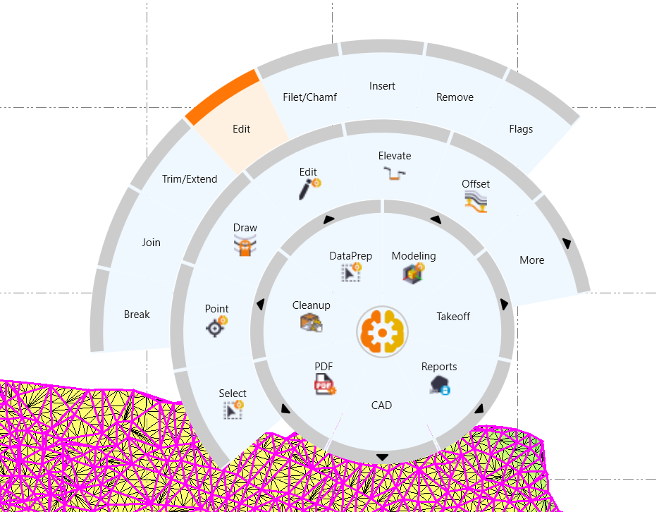
Display showing multi ring expanding menu configuration
This is truly the biggest thing that has happened to TBC in many years and I know you are going to love it and at the same time you get an extra 1" of valuable real estate back to your graphics windows as you transition away from the traditional menu.
For full details - Click Here
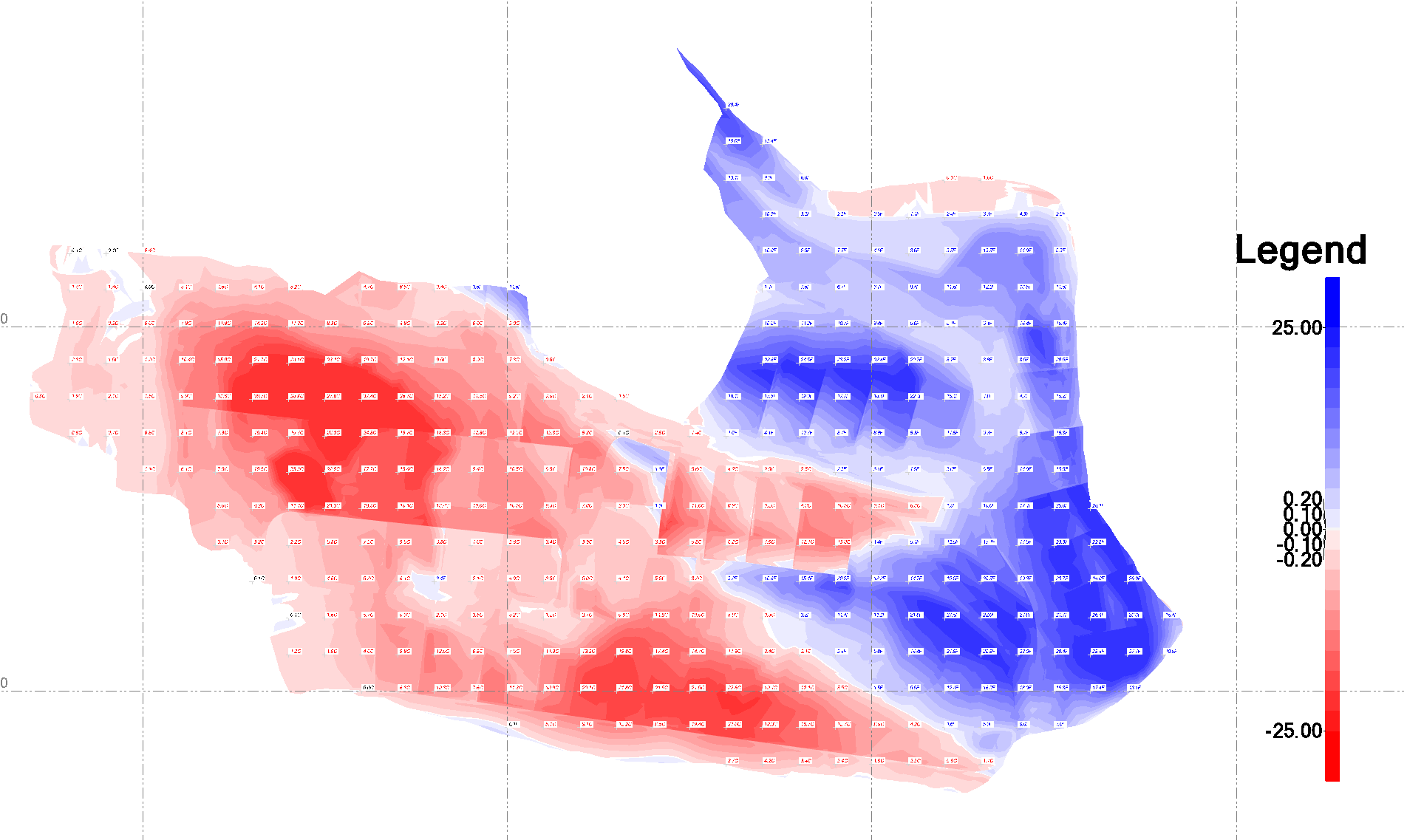
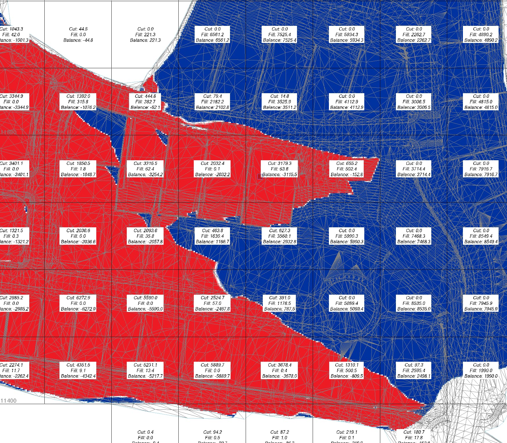
Smart Model - New Cut Fill Maps
Our new Cut Fill Map provides in command volume calculations, high quality reporting, as well as instant recall of the dynamically linked volume results including the ability to quickly apply or adjust shrink swell factors. All surface properties are managed through the surface styles function allowing you to create drawing deliverables faster and easier than ever. The Cut Fill maps have fully customizable color maps, automated labeling and legend placement and can be laid out on a drawing sheet in seconds using the inbuilt capture image to Clipboard and RPS Paste capabilities.
Cut Fill Map with user defined color scheme and legend
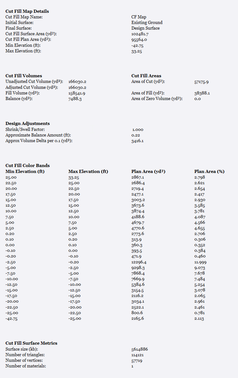
New Cut Fill Map Report
Volumes Manager - New Progress Volumes

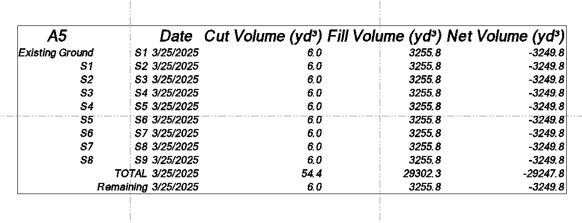
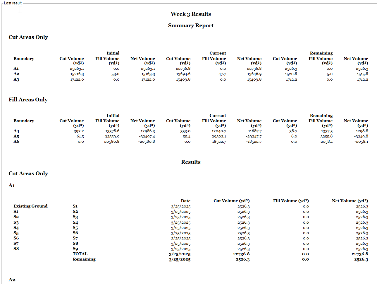
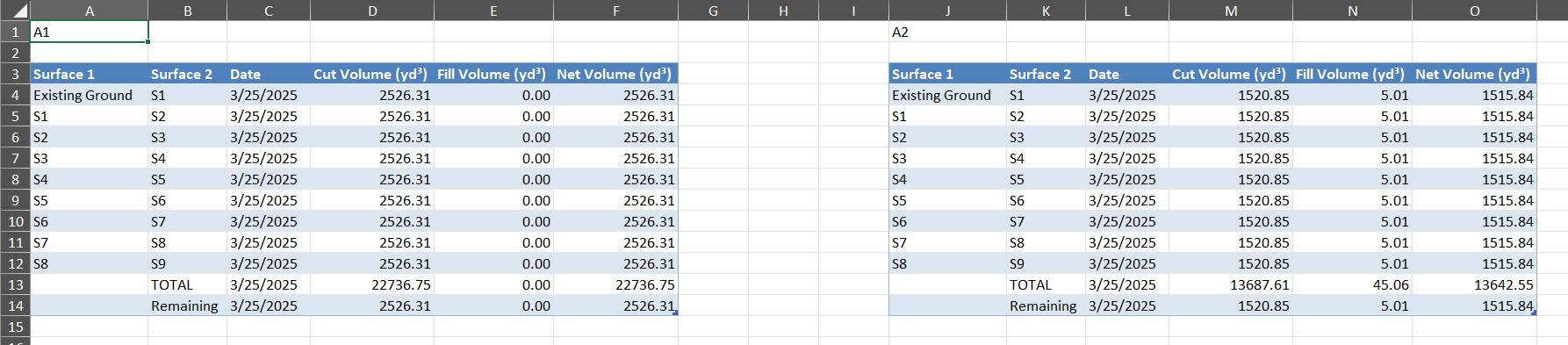
The Volumes Manager command has had a major upgrade with our automated progress volume calculator - select an Existing Surface (start point), Design Surface (end point), and many Work in Progress surfaces (interim surfaces), as well as multiple boundaries, and generate on screen tables of results, high quality reports to Excel or PDF, and stored volume calculations that can be recalled at any time to monitor and track progress of projects quickly and easily, through sequenced or cumulative volume calculations.
On screen volume tables
Detailed progress volume reports
Formatted Excel output
Grid Volumes by Boundary Command Update
Grid volumes by boundary has had a major update that provides the ability to automatically label the volumes inside each of the boundaries selected or the computation cells defined. The labels can be aligned to the orthogonal axes or in relation to a selected alignment. The excel reporting is now linked to the Excel Template described below. providing more compelling reports than ever.
Excel Reports - New Excel Template Use
RPS Excel based reports now use an Excel Template stored in the RPS Settings folder, allowing you to define your own custom page headers and footers (include company details, logos and more), as well as table color schemes and fonts etc.
New Smart Point Manager Command

Create points - Grid or Grid only, Merge points based on horizontal or vertical proximity, point id or feature code, search and replace text characters in point IDs or feature codes, apply prefix or suffix to point ids or feature code. Set Point ID or Feature Codes based on station and offset in relation to one or multiple alignments, guide lines or reference lines.
New Smart Map Command

For survey managers that have field crews that use limited or no feature coding, this provides you with a set of tools that will assist you to create line drawings for pre-construction topo’s, as-builts or progress surveys’
The new Smart Map command allows the generation of line drawings from selected points based on
- Point sequence only - controlled by point to point distance or angle deflections
- Point sequence with feature coding - without a predefined feature code library, uses string numbers or start /end control codes like + or - to determine line breaks, and codes that start e.g. with P to identify point features
- By station and offset - in relation to any number of reference lines or alignments
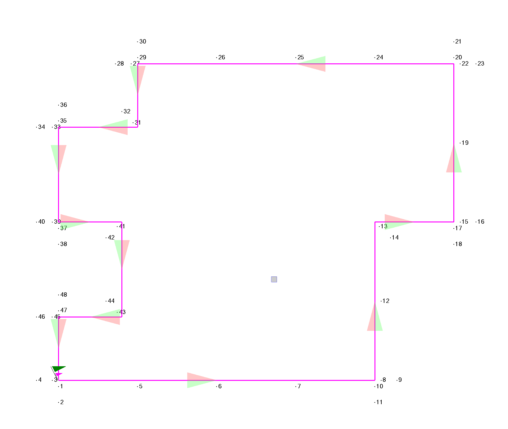
New Smart Stake Command

Create stakeout point data automatically for box structures, buildings, foundations and footings, curb lines or any 2D / 3D design lines with inbuilt smarts for corner staking and offset staking.
Box structure stakeout points
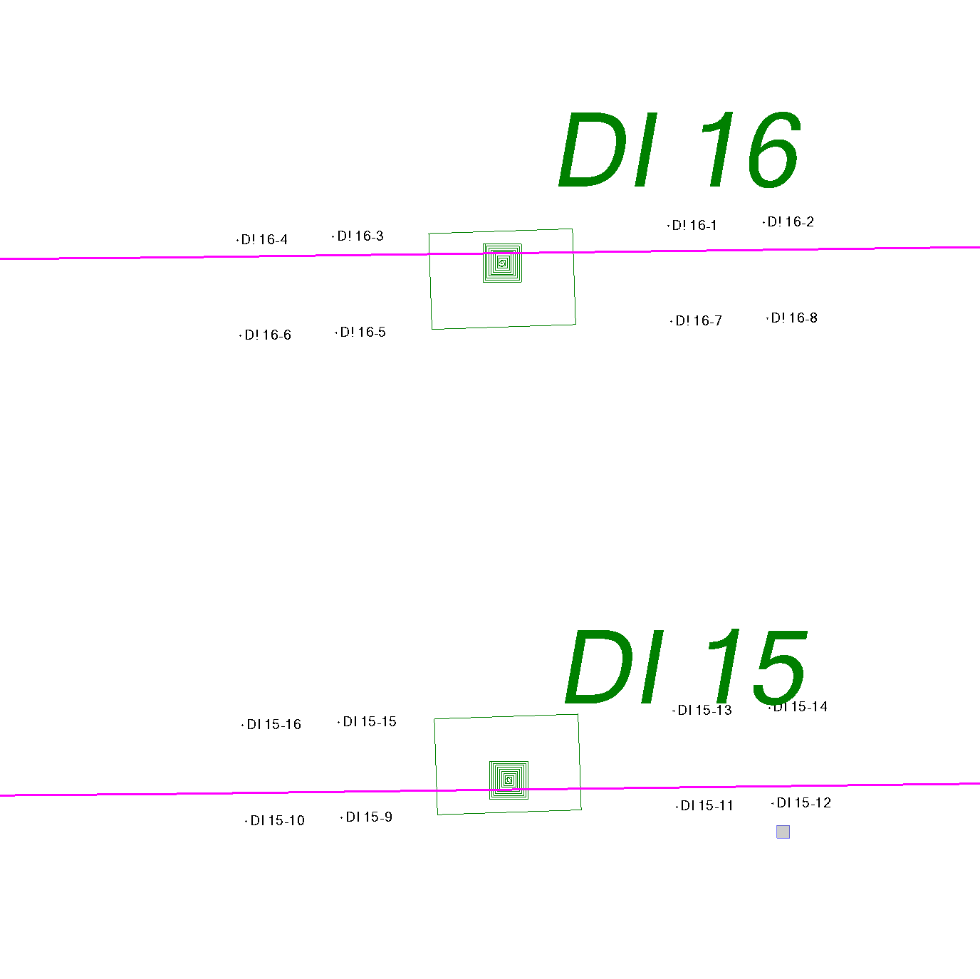
Building stakeout points
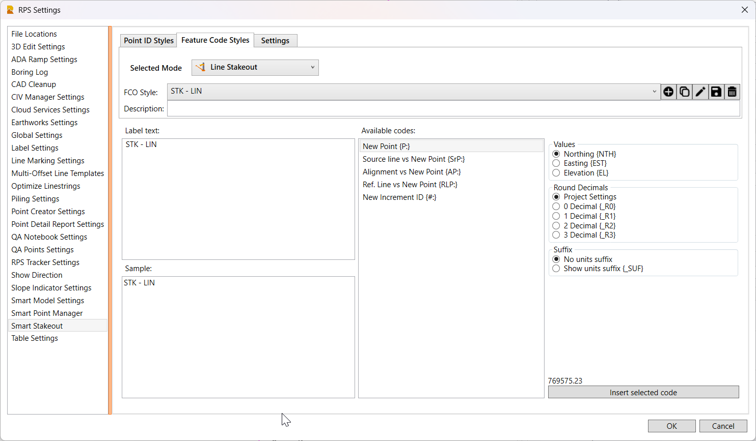
Note:
Smart Point Manager and Smart Stake both utilize our new Smart Naming controls that allow you to create styles for Point ID and Feature Code creation using combinations of user defined text, layer names, line / structure names, reference line names, reference line stations, Counters that increment, coordinates. offsets, slopes, side of line (L/R), units (ft/m) and decimal rounding rules.
Smart Select Command Upgrades

The Smart Select command has received a number of major upgrades for people (Surveyors, Engineers and Contractors) that process point cloud data. Key improvements include
- The ability to take 2D lines and a point cloud and use Smart Filter to compute accurate elevations for the 2D lines. You can create multiple line outputs using Highest, Lowest, Median and Average filters as well as the unfiltered line as a reference to check the results. The filtering process samples at every node of the source line in addition to at intervals along the source line (with or without reference to an alignment for stationing to align where nodes are created on multiple road feature lines so they fall at the same stations). The filtering process also allows for optional secondary filtering that provides a means of eliminating pothole and road debris spikes in the results.
- The ability to slice horizontally through vertical structures, shafts and buildings to create horizontal slice lines - in this case using smoothed, innermost, outermost, average and median lines, that can be used to determine construction to tolerance, under / over break and also deformation / movement between surveys. Slices can be computed at defined elevations or at intervals over a range of elevations automatically.
- The ability to automatically remove points from a point cloud region based on them being inside a closed polygon - designed for removal of high / low points inside popcorn contours derived from point cloud surveys (Lidar, Photogrammetry, Terrestrial Scans or Mobile Mapping). The polygons selected can be filtered by length and closed loop so that only polygons below a certain size are selected. The selected polygons can also be relayered or deleted to remove them from your final survey deliverables.
- The ability to quickly select and remove points from a point cloud using rectangle or polygon select in 3D to despike a surface model where canopy has been removed but some spikes remain.
New Survey to CAD Command
When you bring in survey data from Trimble Access or Siteworks and process the data with the Feature Code Processor, the curved lines that are created are either Smooth Curve, Tangent Tangent, Start Tangent or End Tangent Arcs. All of these curve types are incompatible with AutoCAD. The new Survey to CAD command, reprocesses all of your processed survey linework and converts the curves into arcs that are 100% compatible with AutoCAD, it also creates 2D and 3D deliverable linework that you can use for your export to AutoCAD DWG process.
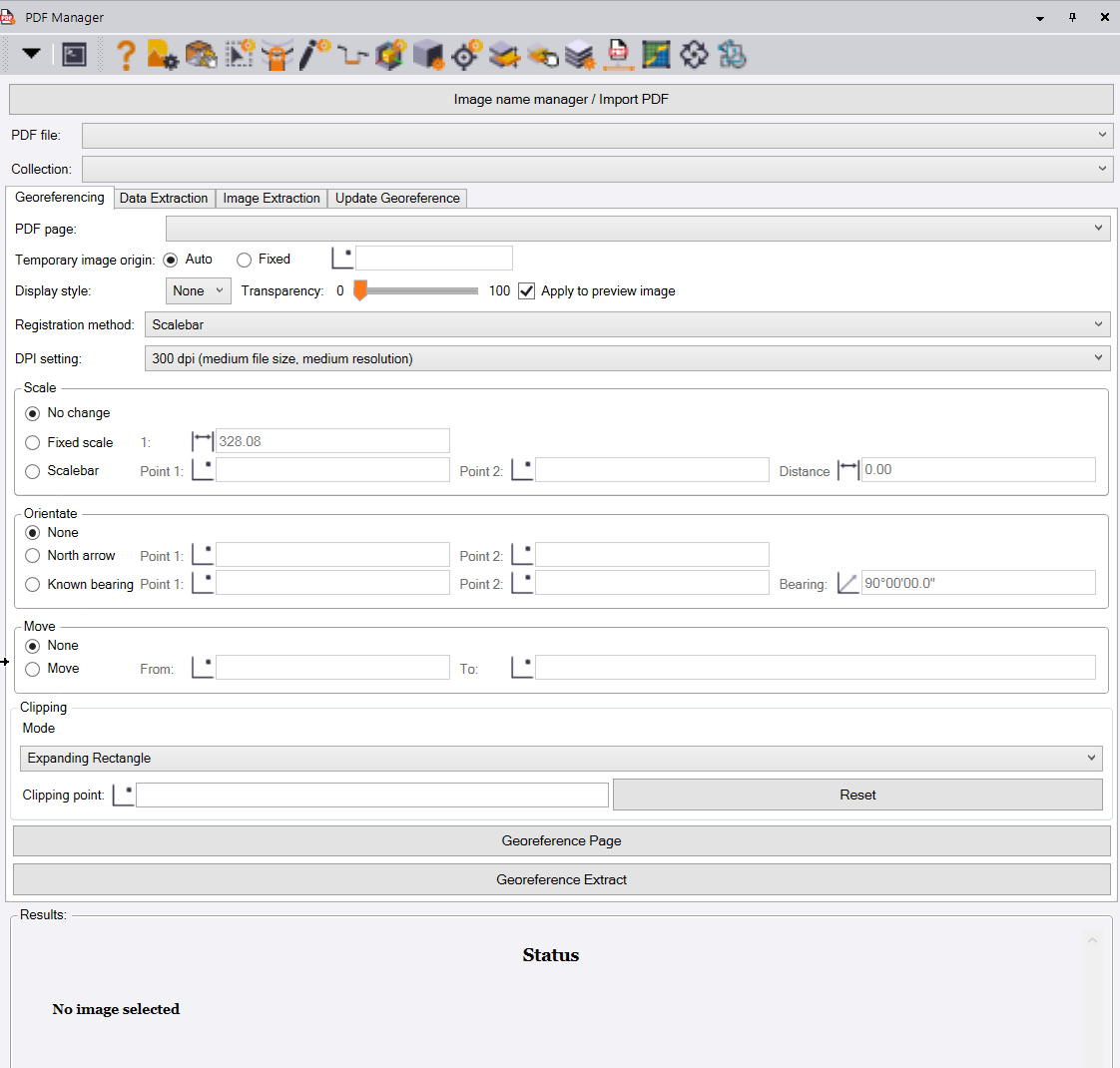
PDF Manager Improvements

In response to your requests, we have added the ability to control the DPI of the placed PDF images - you can now select 96, 150, 300 or 600 DPI to minimize the file size footprint of each placed page.
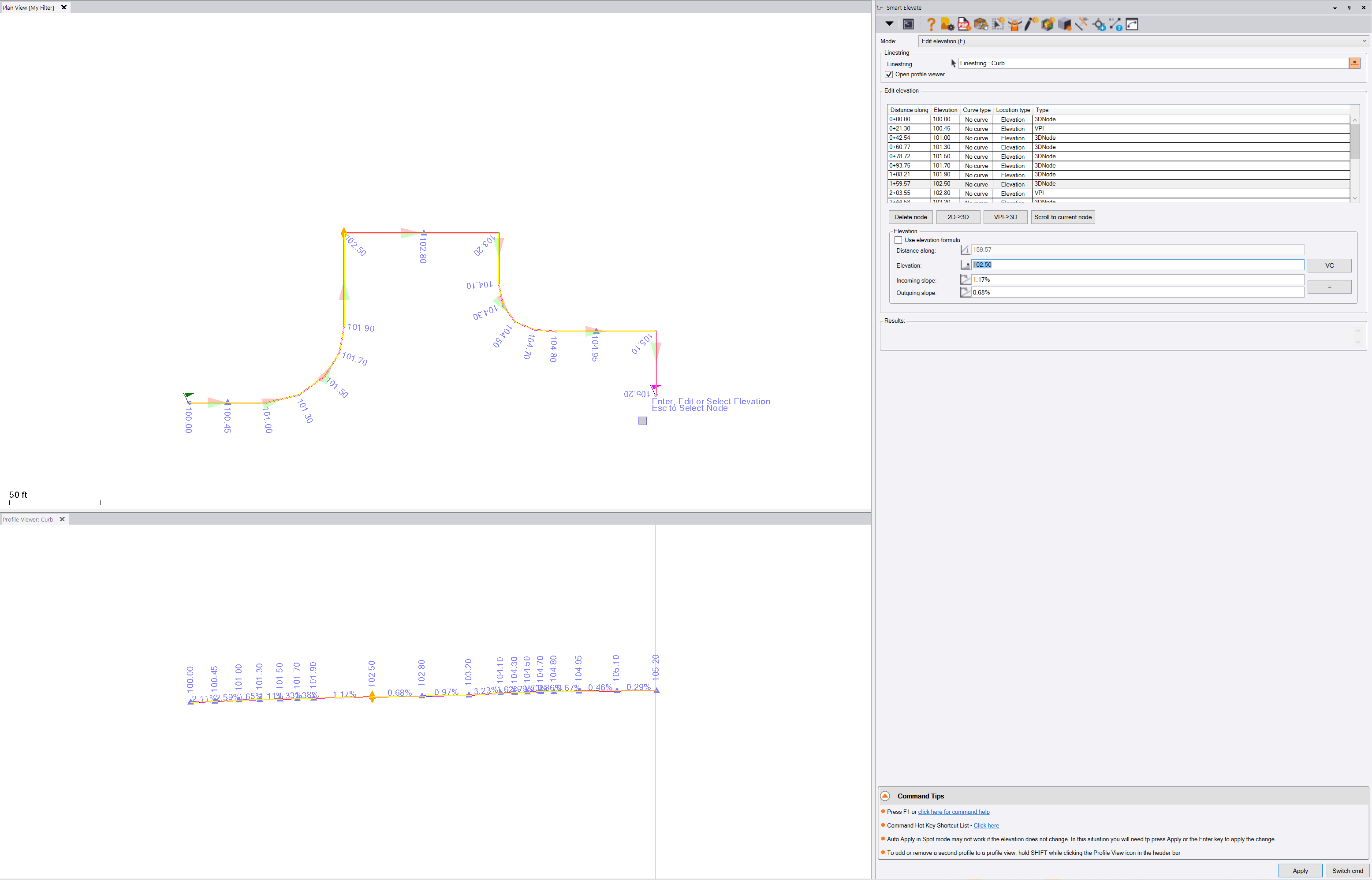
Smart Elevate - Elevation Editor and More!

The Smart Elevate command now includes a new simple to use Elevation editor. The command will now optionally open a profile view for the selected line, and provides a simple / fast way to edit elevations of a line, regardless of whether the elevations are defined as 3D Nodes, VPIs or 2D Nodes. The function also allows you to equalize the slope in / out at a point or insert a vertical curve of a defined length. You can also change the elevation of a point by defining the inbound or outbound slope at the point which will recompute the elevation. The Plan and Profile Views are synchronized so that you can clearly see the selected node in both views with a point marker placed at the point. If you need to add extra VPIs just switch to spot mode, if you need to insert extra points to the line simply switch to Smart Edit - Insert Segment or Line Edit modes.
In addition the Z formula function has been upgraded to allow the input for e.g. cross slope i.e. {Z}+2% will now apply the elevation of the selected point, node or line with a +2% computed over the distance between the node being elevated and the selected location - this allows easy elevating of sidewalk lines from back of curb lines where the cross slope is defined by typical sections.
When running Elevate with Relayer options, you can now select whether you want to copy the selected line to the target line or relayer it, leaving the original 2D line in place. You can also opt to hide the target layer so that as objects are elevated and relayered they disappear from screen, so that you know you have done them.
Numerous other improvements have been made in line with your feedback, requests and defects reported.
Smart Edit Improvements

The Line Edit function - Offset Slope mode has been enhanced to better handle reference lines and alignments that may or may not have the same direction as the source line. The interval process has been improved to provide a better workflow.
Convert to Linestring Improvements

The convert to linestring command has been improved as follows
- We have added the ability to see the number of vertices that have been removed from lines when the vertices removal process is used
- When you select an alignment and convert it to a linestring, it creates a copy of the alignment and converts the copy, leaving the original alignment in place.
- When you convert an alignment to a linestring, we automatically set the breakline approximation parameters internally so that the linestring where it needs to be chorded for spiral elements the resulting linestring automatically approximates to the original alignment.
Header Bar Command changes
![]()
In line with all of the above changes, key commands that you may want access to have changed, so we have refreshed the header bar commands for all commands accordingly. We have also added Smart Model and Volumes Manager to all command headers along with PDF Manager, CAD Cleanup, Smart Select, Smart Draw, Smart Edit, and Smart Elevate since these no provide the majority of your PDF, Data Prep, Elevate, Model and Volume computation needs.
There are also many other small enhancements in this release, we hope you like it!