CIV Robotics Manager

Command Licensing and Default Menu Location
- The CIVRobotics Manager command is part of the RPS Tool Shed Toolbox
- The command is located on the Tool Shed toolbox menu ribbon
- The command is located in the Export menu group
Command Prerequisites
The command creates data files and emails them to the CivRobot that you select. Top do this it utilizes an Outlook email service. Before you run the command you need to setup an Outlook instance and configure your sending email account used to distribute data to / from the Civ Robots in use.
Command Description
Creates and exports stakeout point data and emails the information to a selected CIVRobotics Staking Drone or Robot. Imports CIVRobotic As Staked files and creates As Staked Records for reporting purposes.
Video Demonstration
The following video shows how to utilize the Points to CSV command
Command Interface Description
The CIVRobotics Manager command dialog looks as follows
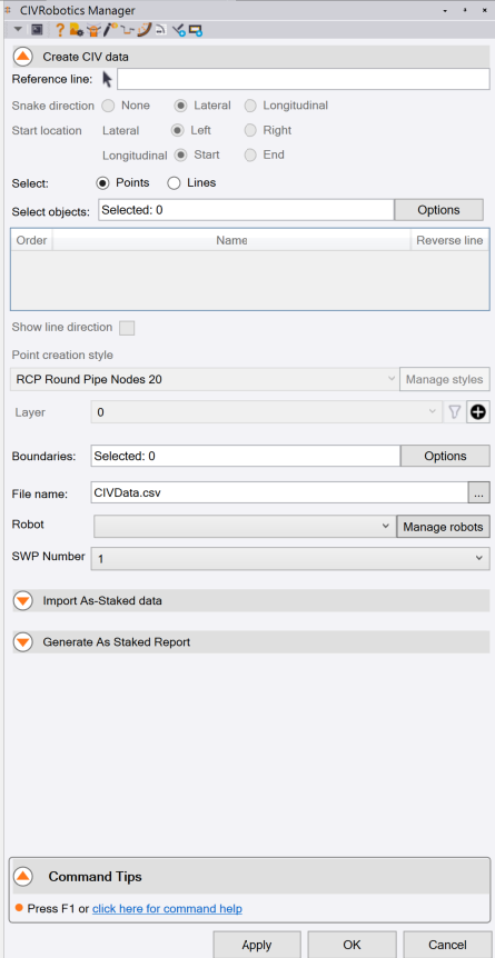
Command Prerequisites
The CIVRobotics file format for points uses Latitude, Longitude in WGS84 (EPSG = 4326) coordinates. In order to be able to create the points, the TBC project must have either a defined Coordinate System or a Site Calibration or both set up prior to running the CIVRobotics Manager command.
All points created through this process will be created in the local coordinates of the project, and are only exported in Latitude, Longitude format. At this time the output file does not support Ellipsoidal Height so all points output are 2D only. The As Staked points captured by the robots during field operations are stored with the height of the staked locations and will be imported as 3D points. Cut Fill differences between the source points in TBC and the As Staked points can therefore be determined, provided that the initial source points are 3D.
Use Case Tips:
The work process to create data for the CIV Robot can be subdivided into three separate workflows
Point Data Method:
Points exist in the project that you wish to select and export to the CIV Robot. These may have been created using the Create from CAD command or the RPS Point Creator command. In this process, the command makes no attempt to optimize the order of the points for the layout robot, the field software for the CIV Robot will manage the routing optimization for the robot based on point proximity to limit the travel distance and angular turns that the robot has to make to navigate between point locations.
Line Data Method:
Lines exist in the project that are not related to a reference line or an alignment, that you wish to create points from for the robot to layout. For example you may have curb and gutter in a parking lot to layout or the foundation lines for a wall. In this case you will use the CIVRobotics Manager command to select the lines, create the points and then send the mission files to the CIV Robot. In this process, the order that you select the lines to be laid out is important, you are creating the path for the robot to follow.
The start and end points of the lines and direction of the line are important to consider when creating this type of mission. Use the CTRL click method of line selection to select the lines in the correct sequence order to provide an efficient path for the robot to follow. You can also create a continuous path line from the source lines (see below) for the robot to follow.
Complex Paths:
For complex robot routing paths, you may wish to create a single linestring that follows the path you would like the robot to take. You can then use the CIVRobotics Manager to create the points in sequence along the path created. You can use the linestring command and the append tracked function to append lines in sequence order to generate the path required. This will allow you to see inefficient path definition before committing the data to the robot.
Line Data Associated With a Reference Line or Alignment Method:
Lines exist in the project that are related to a reference line or alignment, from which you want to create points for the robot to layout. For example you may have striping or curb lines that relate to the alignment for a road or highway. In this case you will use the CIVRobotics Manager command to select the Reference Line and the Lines that you wish to layout. The points will be computed at key locations in reference to the selected reference line or alignment e.g. at Tangent Points or Interval Points along the alignment.
In this process, you have options to create a snake pattern using the selected lines and reference line or alignment. The order that you pick the lines will dictate the point numbering, however the direction of increasing or decreasing station of the reference line will dictate the snake pattern between the points for the robot to follow because the lines are sorted left to right or right to left and the longitudinal controls determine the start to end or end to start ordering of the point data for the mission.
Reference line:
If you wish to compute the stakeout points in relation to an alignment or reference line, select the reference line here. The reference line can be an alignment, polyline, 3D polyline, CAD line or a linestring. Once a reference line has been selected, the snake pattern (Lateral (offset based) or longitudinal (Station based)) can be defined using start / end and left / right start point definitions
Snake direction:
The snake directions available are None, Lateral or Longitudinal. The snake direction dictates the order of the points in the mission file created by the export process.
Note: The point numbering of the points created is always based on the order in which the lines are selected.
Note: The order of the points in the mission file is always based on the snake pattern definition.
The snake patterns are as follows
None:
If None is selected, the points will be created along each line in the list and will be stored in the mission file in the order that they are created. In this case, you can use the CIV Robotics field controller software to optimize the route through the points in the field. The order in which you selected the lines, and the direction of the source lines will then be important in terms of the order of the points in the file. You can reverse the direction of the selected lines and change the order of the selected lines to control the path taken by the robot while laying out the points.
Lateral:
The Lateral snake pattern will start at one end of the reference line and snake either left to right, right to left or right to left, left to right depending on the settings chosen here. You can also elect to start the snake pattern at the start or end of the selected reference line based on the settings defined here. For road features where the lines come and go longitudinally, this method is recommended. The selected lines are sorted left to right by the software so the order of line selection is less critical for this method.
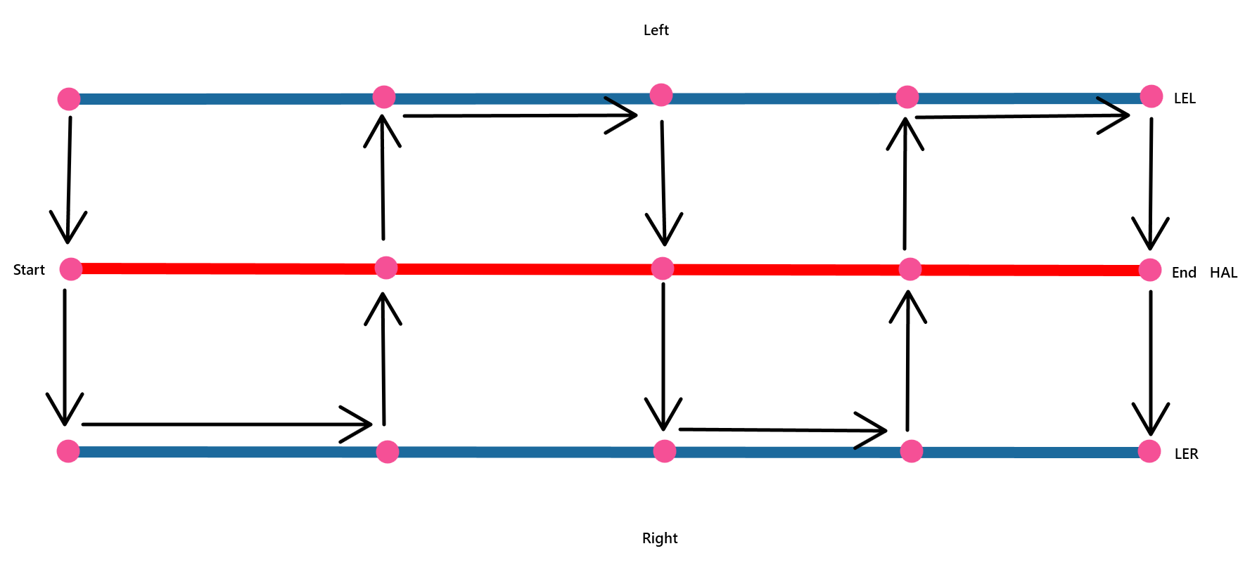
Lateral Pattern - Start Point = Start and Left
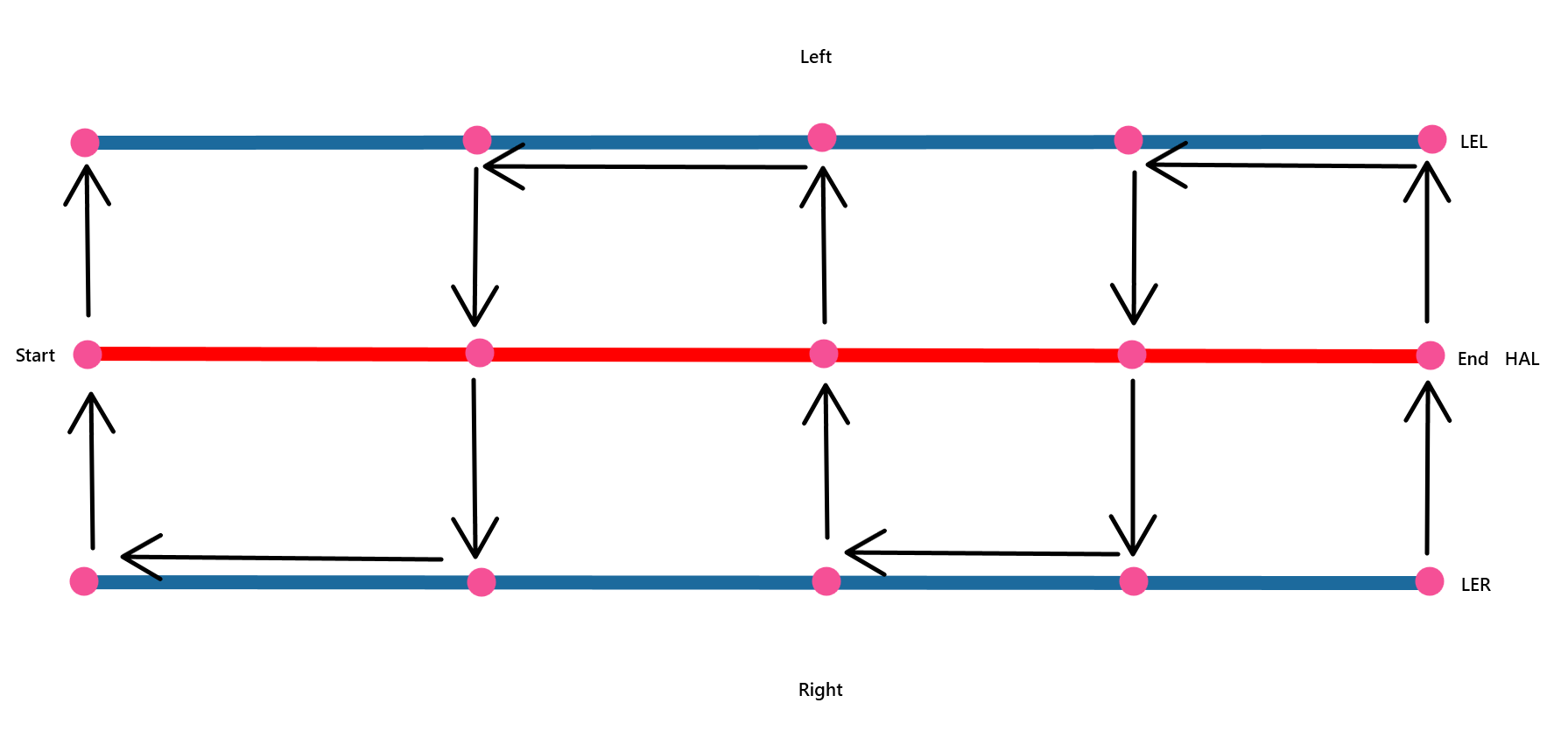
Lateral Pattern - Start Point = End and Right
Longitudinal:
The longitudinal snake pattern will start at one end of the reference line and snake either up and down, up and down or down and up, down and up depending on the settings chosen here. You can also elect to start the snake pattern at the start or end of the reference line based on the settings defined here. For road features like striping that are continuous for all selected lines along the selected reference line, this is a good option to select. Where the selected lines are broken, or where they come and go along the reference line, we recommend the None or Lateral snake pattern.
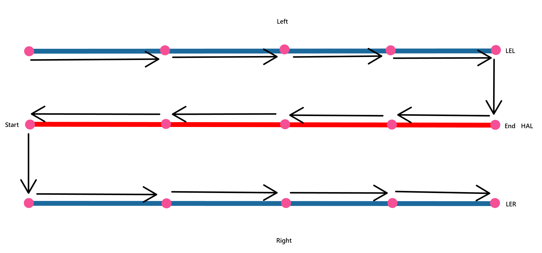
Longitudinal Pattern - Start Point = Start and Left
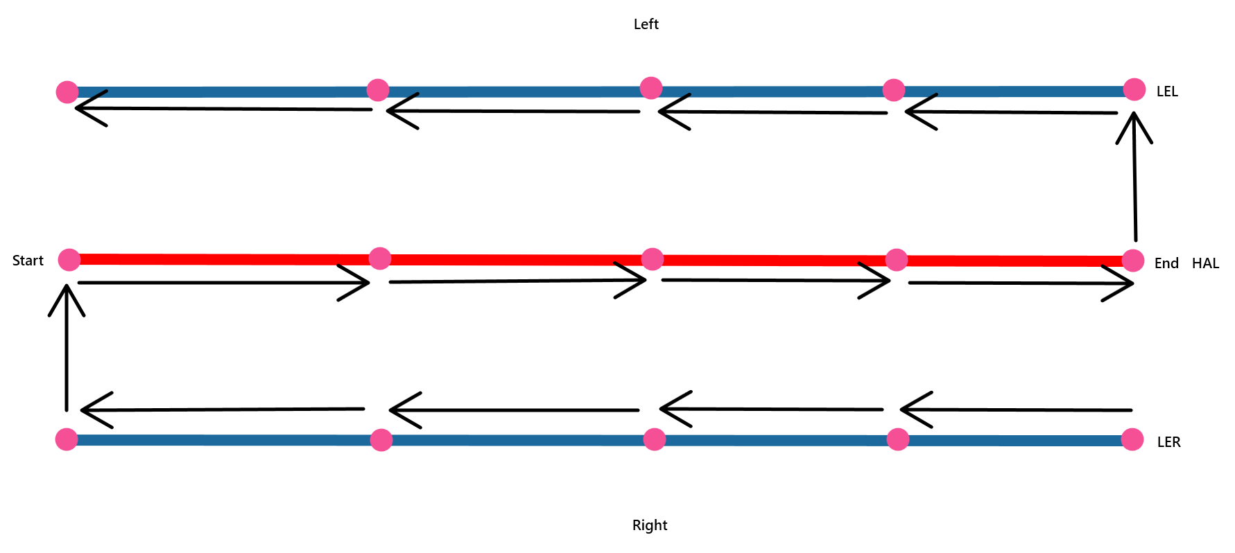
Longitudinal Pattern - Start Point = End and Right
Start location:
Depending on the option that you selected for the Snake direction, choose the appropriate settings here for either Lateral or Longitudinal start location.
Lateral:
The options are Left or Right for the lateral start location. This applies to both the lateral and longitudinal snake pattern.
If you choose Left, the snake pattern starts at the left most line and snakes to the right across the road, when the last line is encountered the robot will move up the line and then traverse the road from right to left stopping at each line in sequence. This will repeat up the road.
If you choose Right, the snake pattern will be the reverse, starting on the right and traversing to the left across the lines selected etc.
Note: The selected lines are sorted Left to Right or Right to Left according to the settings selected. regardless of the order in which the lines are selected and displayed.
Longitudinal:
The options are Start or End for the longitudinal start location. This setting applies to both the longitudinal and lateral snake patterns.
If you choose Start, the longitudinal pattern will start with the left most or right most line in the list (depending on the lateral start location) and navigate up station along the reference line direction.
If you choose End, the longitudinal pattern will start with the left most or right most line in the list (depending on the lateral start location) and navigate down station along the reference line direction.
Select Points or Lines:
The exporter can transfer points that already exist or can create points from selected lines. The creation of points uses the same controls as the Point Creator command (Click Here for more details) Choose the option that you require for the mission being created.
Select:
Select the points or lines that you wish to use for the export. Points will be transferred directly, lines will be used to derive points that will then be transferred. If you wish to select data using advanced methods (Advanced select, Select by layer, Select by elevation etc.) click Options.
If you select points, the points are not sorted into any specific order. The field system will provide point data route optimization for the robot from the points in each mission. The route optimization will create an optimized stakeout path for the robot to follow that minimizes travel distance and angular turns.
If you select lines, from which points will be created, you have some options on how to optimize the stakeout path for the robot using the command settings.
Pick the lines graphically, one by one, in the order that you want the robot to stake them out i.e. pick lines from left to right across a road, or where the lines are not following an alignment, pick them in the order that you wish to stake them out. Once selected, you can elect to show the line direction (see Show line direction checkbox below) for each line and then use the line list reverse line checkbox to change the direction of lines if you want to stake them longitudinally (up one line and down the next etc.). If you intend to stake the points using a lateral snake pattern (Left to Right, Right to Left) up the road then the forward and reverse direction of the lines can be ignored.
You can also use the Create linestring command and use the Append Tracked command to create a path that you want the robot to follow, and then use that path line to create the points that you want to have laid out (see the video above for more details)
Line list:
The line list populates as you select lines graphically. You can see the order of the lines (top to bottom) and the name / code of each line selected. For each line you can see whether they will be processed in a Forward or Reverse direction. To see the direction graphically, check the Show line direction checkbox below. To change the direction of a line, click the Reverse line checkbox in the line table. Note that when you have multiple lines selected, highlighting a line in the list will display the line in the highlight line color as defined in RPS Settings.
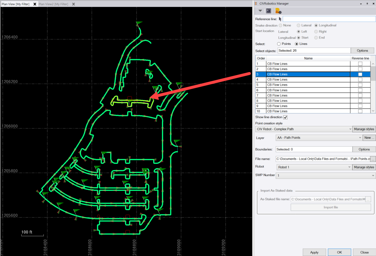

The RPS Settings provide the ability to create primary and secondary highlight colors to supplement the standard TBC single selected items color when working with multiple selections. In this case the secondary highlight color Yellow is used to highlight the line selected in the line list so that you can see that stand out against all of the lines selected (light green lines)
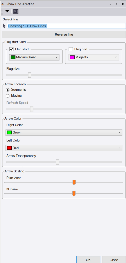
Show line direction checkbox:
You can turn on the line direction indicators by checking this checkbox. The indicators display settings are controlled by the RPS Settings functions accessed using the RPS Settings icon in the command header bar. You can control the color of the arrows, the size of the arrows and the presence of a start and end of line flag (Start flag is useful for closed lines) to assist your understanding of the lines.

For full control over the arrow types and sizing of arrows and flags use the Show Direction command in the RPS Tool Shed Toolbox. Click Here for more details.
Point creation style:
Select the point creation style that you require. Point creation styles are created within the RPS Settings function or by clicking the Manage styles button (which takes you to RPS Settings also). The Point creation style defines which points will be created along the selected lines or alignments and how those points will be coded and how the Point ID and Feature Code fields will be defined for each point created.
Manage styles:
When you select Manage styles, you will be taken to the RPS Settings for the Point Creator tool. If you click the RPS Settings icon ![]() in the header row of the command that will also take you to the same location.
in the header row of the command that will also take you to the same location.

The settings for the point creator tool are stored in the RPS Settings folder as defined by the File locations setting. The settings are stored outside the project so that once defined they can be used inside any project thereafter.
Defined styles:
The defined style defines the points that will be created from a wide selection of options. you can create as many styles as you may require, each with different selections of points and intervals as well as naming conventions.
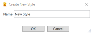
To create a new style click the ![]() button and then enter the style name in the following dialog
button and then enter the style name in the following dialog
To copy an existing style to start the definition of a new style click the ![]() button and then enter a name for the new style in the following dialog
button and then enter a name for the new style in the following dialog
To Edit the name of an existing style, click the ![]() and edit the name of the style in the following dialog
and edit the name of the style in the following dialog
To Save updates or changes to a style, click the ![]() button.
button.
To Delete the selected style click the ![]() button.
button.
Description:
Enter a description for the style for additional detail beyond the style name.
Point ID:
The definition of Point ID provides a template that will be used for all the points to be created. The definition can be a simple Point ID like 1, 1000, 10000 or A1 etc. but it can also include additional information as defined with additional tags as follows. Hover over the ![]() button in the dialog for more details. The codes shown below should all be in upper case letters.
button in the dialog for more details. The codes shown below should all be in upper case letters.
{#} Point number, starts at 1
{#.NNN} Point number, starts at number NNN i.e. {#.10} starts at 10
{#.NNN,INC} Point number, starts at NNN and increments by INC value i.e. {#.10,2} will number 10,12,14 etc.
{NAME} will include the name of the source line for the points i.e. a line called CB will use CB for all of the points on that line. You can use a code set like {#} {NAME} to create Point IDs like 1 CB.
{CODE} will include the key location coding defined below for the point types being created e.g. RP for Radius Point or IP for Interval Point and so on. You can use a code set like {#} {CODE} to create Point IDs like 1 RP.
Codes defined using { } brackets are all upper case letters.
Any text or other characters included in the definition will be treated as text prefix or suffix text to the Point ID definition i.e. CHK{#} will create points CHK1, CHK2 etc.
Restart point numbering with each line checkbox:
Check this checkbox if you wish to reset the Point number to the starting value for each line that you create points for - checking this allows you to number the points along each line in the same way starting from the same value. Note that this will create non unique Point IDs which may make tracking of as staked results more difficult later on.
Feature code:
You can define the Feature code that will be used for each point created. We recommend that you use one of the following or a combination of the following. Note that we automatically write the source line name into the Description 1 attribute for the points created and the station along the line or the station from the selected reference line or alignment into the Description 2 attribute. Use the key location code {CODE} with or without a Prefix like STK {CODE} for Stakeout Points or CHK {CODE} for As Built Check points etc.
{CODE} to add the key location code for the point e.g. RP for Radius Point or IP for Interval Point etc.
{NAME} to add the name of the source line used to derive the point e.g. CB
{STA} to add the station of the point in relation to the selected reference line or alignment.
Offset distance from reference line:
When working with a reference line, you can limit how far offset from the left or right side of the reference line points will be created using this setting. Enter a value e.g. 100’ or 100m to limit the offset range.
Key locations along line:
The point creator tool creates points along selected lines and alignments for both horizontal control and vertical control locations for all elements of the lines including straight / tangent, spirals, arcs, vertical arcs and vertical curves. It also creates points at intervals along the line or at stations along the selected reference line and also the High or Low inflection points of the selected lines. You can select any combination of key location types within a style and define intervals as required for that style. For each key location you can enter a code value which is picked up by the {CODE} field in the settings described earlier.
Horizontal locations - Line:
Begin
End
Nodes
Point on Tangent
Station Equation
Defined Stations
Straight Interval / Enter interval value
Curve Interval / Enter Interval or Number of segments e.g. 4
Note: the ability to enter different interval values for straight and curved sections of lines and the ability to use interval or number (of segments) for curved sections of lines allows you to create stakeout data as needed for these types of element independently.
Horizontal locations - Arc:
Point of curvature
Point of tangency
Point of intersection
Radius point
Radius point elevation 2D or 3D
Compound curve
Reverse curve
Horizontal locations - Spiral:
Tangent to spiral
Spiral to tangent
Curve to spiral
Spiral to curve
Spiral to spiral
Point of intersection
Vertical locations - Line:
Point of beginning
Nodes / VPIs
Grade break
High point i.e. an inflection point of line segments / VPIs that form a crest
Low point i.e. an inflection point of line segments / VPIs that form a sag
Vertical locations - Arc:
Point of curvature
Point of tangency
Point of intersection
Radius point
High point i.e. crest of vertical arc
Low point i.e. sag of vertical arc
Vertical locations - Vertical Curve (Parabola):
Point of curvature
Point of tangency
Point of intersection
High point i.e. crest point of vertical curve
Low point i.e. sag point of vertical curve
Layer:
Select the layer on which to place the created points. If you require a New Layer or New Layer Group, click the New button to open the New layer control.
For full details on how to use the New Layer control Click Here

Boundaries:
If you wish to group the points that get created into separate missions based on boundaries, you can select one or more boundaries here. Note that points will be created for the full length of all lines selected, but only those that lie within the different boundaries selected will be transferred. The points in each boundary will be exported to a separate mission file that derives its name from the name of the boundary line in which they are located. Name the boundaries so that they have unique names, so that the missions can be clearly identified on the CIV Robotics controller.
The file name defined below and the boundary name will be combined to create the file name for each mission file i.e. boundary called Section 5 and a File Name Road will create a mission file called Road_Section 5.csv.
If you select multiple boundaries, the snake patterns defined earlier will exist within each resulting mission file. If the boundary lines selected happen to fall on a station at which points are created, they will be placed in the mission file closest to the start location (Start or End) of the reference line.
File name:
Enter the file name for the csv file that will be created. The file will be saved to the project folder for the project. You can right click in the file name field and select Browse … to browse your computer for the location in which to store the mission files to be created or select Project data to select the TBC project subfolder location.
The file name selected and the boundary name (above) will be combined to create the file name for each mission file i.e. boundary called Section 5 and a File Name Road will create a mission file called Road_Section 5.csv.
Robot:
You can define any number of robots to which you may want to send mission data. The robots are defined using RPS Settings or the Manage Styles button next to the robot selector.

You can add a new drone definition using the ![]() button
button
Fill in the drone details in the Create new drone dialog shown

Name:
Enter the name of the drone
email:
Enter the email address for the drone
Owner:
Enter the name of the owner of the drone
OK:
Click OK to complete the new drone creation process and close the dialog
Cancel:
Click Cancel to close the dialog without saving the new drone
You can copy an existing drone definition using the ![]() button
button
Select the drone that you wish to copy in the list of already defined drones. Click the copy button. The create new drone dialog defined above will open and be pre populated with values that can be overwritten as required.
You can edit an existing drone definition using the ![]() button
button
Select the drone that you wish to edit in the list of already defined drones. Click the edit button. The edit drone dialog (identical to the Create new drone dialog above) will open and be pre populated with the current values for the drone that can be overwritten as required.
You can delete an existing drone definition using the ![]() button
button
Select the drone that you wish to delete in the list of already defined drones. Click the delete button to remove it from the list.
Maximum number of points:
There is no limit to the number of points that can be created in a single mission file. You may however wish to limit the number of points per mission, if so enter the limiting value here e.g. 10000
Display file checkbox:
On completion of the file creation process, if you check this checkbox, the file will be opened in Excel on your computer so that you can review the output data.
Data file 5th column contents:
The CIVRobotics file format is typically a 4 column, comma separated file format containing P,Lat,Long,SWP data where
P = Point ID
Lat = Latitude
Long = Longitude
SWP = Special Way Point (Colors from 0 - 6)
The SWP colors are as follows and are used to display points of different types on the CIV Field controller system.

The CIV file format was recently extended to include a 5th column of information that they use in their Dominant Color workflow for Solar Farm piling projects where the robots are used to place colored markers indicating the type of pile required at each location (Length and cross sectional size and shape). In this workflow, the piles are color coded - each color represents a different type of pile. In a single area, there can be e.g. 12 types of pile to place for different purposes. In the data file, we can use the 5th column to output the pile colors for each location e.g. Light Blue, Dark Blue, Red, Yellow, Purple, Orange etc. In the dominant color workflow, the CIV Field Software reviews all of the point data to find the dominant color. For all points staked with the dominant color, the robot navigates, sprays a paint spot and moves on automatically. For points that have a non dominant color, the robot navigates, sprays a spot of paint and pauses to tell the field operator the color required. On acceptance, the robot moves on allowing the operator to pull a colored nail with flagging and place at the staked location, indicating to the shakeout crew which type / color of pile is required at that location.
To support this workflow, you can output the feature code, description 1 or description 2 field for each point to the mission file. The values selected will be used in the dominant color workflow. For example code all the points using the color of the pile required and use feature code as the 5th column data,
The default for this value is none for all other workflows.
Generate email checkbox:
You can elect to send the file to the drone / robot directly via email. The current system supports your Outlook instance and packages the mission file(s) created into an email and sends it to the nominated email address for the drone / robot. The email address for the robot is defined below.
Once checked, outlook needs to be running in order for the email to be created and sent. If you intend to use any other email system e.g. Gmail, they are currently not supported, so create the files and attach to an email manually to send to the robot.
From (sender) email address:
Once Outlook is opened, the routine can determine which email accounts are setup in Outlook, they will be presented here. Select the account that you wish to use as the sender for the email.
Automatically send email checkbox:
The email will be created and will open in Outlook for you to review prior to sending. If you do not wish to review the emails before sending, check this checkbox, the emails will then be created and sent automatically provided that Outlook is open during this process.
Use Case Notes:
If you would like to test or demonstrate the round trip process of the command, in the settings file that is created for the CIVRobotics Manager command, you can change the setting that states “GenerateSampleFiles”: false, to “GenerateSampleFiles”: true,. When you run the export to CIV process, at that time the command will also create a sample file for each file generated that has artificially “dithered” values to replicate the CIV As Staked data format, which you can use to import data back into TBC as a round trip check or trial or demonstration of the reporting process.
OK:
Click OK to complete the drone definition and settings and close the RPS Settings dialog
Cancel:
Click Cancel to close the RPS Settings dialog without saving any changes
SWP Number:
The file format for the mission file is a CSV file that has the following fields
Point ID, Latitude, Longitude, SWP Number, Code.
The SWP (Special Way Point) Number is a numerical value from 0 through 6. Each numerical value represents a color that the points will be drawn in on the graphics screen of the CIV Robot controller. The colors are mapped as follows.
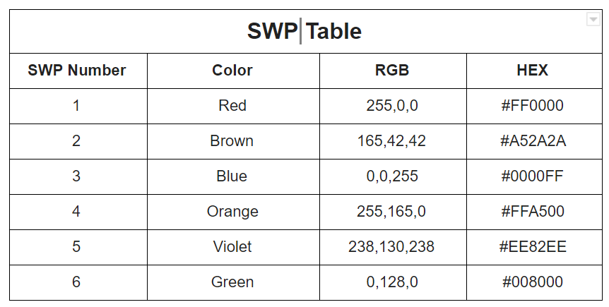
You can select the SWP color from the pull down list.
Import As Staked data:
Still in development
As staked file name:
use the […] button to browse for an As Staked file from the CIV Robot.
Apply:
Executes the command, generates the points, generates the mission file(s) and prepares for the selection of another set of data.
OK
Executes the command, generates the points, generates the mission files and closes on completion
Cancel
Closes the command without further execution.
Use Case Videos
The following videos show the use of the Points to CSV command in a work process context
In the following video we show
- How to setup and select a coordinate system in TBC using the Change Coordinate System command
- How to import or enter coordinate pairs (PNE and PLLH) for control points and GPS Points in Lat Long using the Create Point or Import command (and Import Script Editor)
- How to carry out a Site Calibration using the coordinate pairs using the Site Calibration command
- How to set up an Import Script and then Import a points file from a CSV file format using the Import Script and Import commands
- How to setup an Export Script and then Export a collection of points for solar farm piles in P,L,L,SWP,Dominant Color format for use in the CIV Robotics system.
- How to edit the created CSV file to add a EPSG 4326 header row
- How to setup and manage Project Settings for Latitude, Longitude coordinates to achieve the desired accuracy.
The process shows how to convert imported coordinates in State Plan out to a calibrated WGS84 coordinate file for use in the CIV Robotics system.
Feedback and Enhancement Requests
If you would like to provide feedback on the use of the Points to CSV command or to request enhancements or improvements to the command please click Reply below.