Quick Alignment Command

Command Description
Converts one or more 2D or 3D linestrings or Polylines into alignments with optional alignment labels in a single step.
Command Notes
When you import CAD files or extract linework from PDF files, you will often have the elements that make up the centerline alignments of roads or alignments of retaining walls etc. The first step of the modeling process is to connect those elements together using e.g. Smart Edit - Join to create continuous lines from the CAD Line and Arc elements provided. Once they have been joined together, the next thing to check is that the lines have the correct line direction (direction of increasing station from the plans), if not you can use the Show Direction or Reverse Line commands to change the direction to what is required. You can use the Reverse Line function in this command to inspect and then reverse lines as needed. Use the Show Direction function to show the current direction of increasing station.
This command makes it extremely easy to create one or multiple alignments from the imported CAD files.
As a follow on, if your alignments have profile drawings (either CAD or PDF extracted data), then you can use the Smart Profile command to add the Vertical Alignment (Design Profile) or Existing Profile or Pipe Profiles to the path of the alignment as an extra step to create 3D data that you can use to build your roads or sewer runs.
Release History
Dec 2025
First release with RPS Command Library 2025.4
Command location
The Quick Alignment command is part of the RPS Modeling Toolbox
- The command can be located on the Smart Suite and Modeling menu ribbons
- The command is in the Design command group on the Smart Suite menu
- The command is in the Corridor command group on the Modeling menu
Video Demonstration
The video below shows how to use the Quick Alignment command.
The video below shows how to use Quick Alignment with Smart Elevate and or Smart profile to create 3D Alignments using Profile Drawings
Command Interface Description
The Quick Alignment command dialog looks as follows
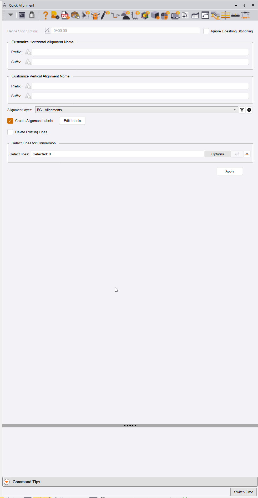
When you select multiple alignments, all alignments will get the same start station, unless the lines are linestrings, that have ben assigned the start station property via the properties pane.
When you process single alignments one at a time, you can assign a different start station to each alignment.
If you first use the TBC “backdoor” method of assigning stations to linestrings i.e. if you name a linestring starting with two underscores e.g. __HAL then it will reveal its station property, you can assign a station to the linestring, and that will be detected by the Quick Alignment command to create the correct start station for the alignment(s). Note that many RPS commands, that edit, modify or create linestrings will do this automatically, so you may find that a linestring you have in your project has already revealed its Station property.
Pre-Requisites
The command will convert Polyline or Linestring objects into an alignment object. If the Linestring has vertical Geometry, that will be used to create the vertical Alignment component of the new alignment object.
Name the lines with the names that you want to use for the alignments.
If the source lines are linestrings, you can set the start station for the linestring in the poperties pane if they are non zero, use the properties pane to achieve this. Note that if the station property is not visible, change the name of the line by adding two underscores to the front of the name to trigger the station property to become visible. Normally, if you have edited any line using RPS Tools the station property will have been activated.
Main Dialog Controls
Alignment Properties
Ignore Linestring Stationing Checkbox
Linestrings can have a station property. If the linestring has a defined start station property it will be used and will override the value entered here when the checkbox is disabled (the default behavior).
When this checkbox is enabled, the linestring station will be ignored, and the value entered here will be used instead.
Note - if each alignment has a different start station, you will need to process the lines one at a time, or use the linestring station property first before comnverting the lines into alignments.
If the Start Station property of a linestring is not displayed in the properties pane, you can add two underscores to the name of the linestrng and then on acceptance of the name change, the start station property will be revealed.
Alignment Start Station
Enter the start station for the alignment(s) you are creating. Note that all of the selected lines will receive the same start station.
Note that the alignment start station can only be set when the Ignore Linestring Stationing checkbox is enabled.
Prefix for alignment name
If the lines that you select have a name, that name will be used for the alignment that is being created. If you wish to prefix the line name with some additional characters, enter them here. i.e. If the source linestring is named HAL A, the alignment will be named HAL A, if you add a Prefix XXX - then your alignment will be named XXX - HAL A.
Suffix for horizontal alignment name
If the lines that you select have a name, that name will be used for the alignment that is being created. If you wish to suffix the line name with some additional characters, enter them here. i.e. If the source linestring is named HAL A, the alignment will be named HAL A, if you add a Suffix - XXX then your alignment will be named HAL A - XXX.
Alignment Layer
Select the layer on which you want to place the alignments that are created by the command. You can create a new layer and use the layer filters through use of the buttons to the right of the layer selector combo box.
The RPS default layer for this is FG - Alignments
Note
If the source lines have vertical components (Grade Breaks, Vertical Curves or Vertical Arcs), they will be used to create a vertical alignment for the alignment.
Prefix for vertical alignment name
If the lines that you select have a name, that name will be used for the vertical alignment that is being created. If you wish to prefix the vertical line name with some additional characters, enter them here. i.e. If the source linestring is named Narrow Leaf Drive, the vertical alignment will be named Narrow Leaf Drive, if you add a Prefix VAL - then your alignment will be named VAL - Narrow Leaf Drive.
Suffix for vertical alignment name
If the lines that you select have a name, that name will be used for the vertical alignment that is being created. If you wish to suffix the vertical line name with some additional characters, enter them here. i.e. If the source linestring is named Narrow Leaf Drive, the vertical alignment will be named Narrow Leaf Drive, if you add a suffix - VAL, then your alignment will be named Narrow Leaf Drive - VAL.
Create Alignment Labels checkbox
When checked, the alignments that are created will be labeled using the alignment label settings (defined in Project Settings - Abbreviations - Alignment Labels). This will place station labels and tick marks along the alignment as well as label all PC, PT, POB, POE and Station Equation points along the alignment.
Edit Labels button
If you wish to modify the way that the alignment labels look, or which labels are applied. click the Edit Labels button to access the Alignment Labels settings editor (normally accessed using Project Settings - Abbreviations - Alignment Labels).
Delete Existing Lines checkbox
When enabled, the source lines will be deleted once the alignments have been created.
If you wish to retain the source lines after the alignments are created, leave the checkbox unchecked.
Select Lines for Conversion
Select Lines
Select the CAD Lines, Polylines or linestrings that you wish to convert into alignments. All line types except alignments will be automatically converted into 3D linestrings when selected and used in this command.
Show Direction Arrows
If you are unsure of the direction that the lines are defined, enable the show direction arrows button at the right end of the line selector box.
Reverse Line button
When you select lines one at a time, the line direction arrows indicate the direction of increasing station. If you wish to reverse the line, click the Reverse Line button. The show direction arrows will indicate the changed direction for the line. The Reverse Line button only works when a single line is selected. Once a line has been selected and reversed, the command focus returns to the line selector, so that you can click a different line and review its direction. You can sequentially click any number of lines, and reverse those that need reversing.
Use the Options button to access the advanced selection techniques like Select by Layer, Select by Elevation, Select by Polygon etc.
Information Area
In the information area, you will see the results of each process run as it is executed. or example it will show how many lines were selected, how many horizontal alignments and how many vertical alignments were created by the process.
Other Command Controls
Apply Button
Click the Apply button to execute the alignment / alignment label creation process. On completion, the command will ready itself for another selection and repeat process.
Switch Cmd Button
Click the Switch cmd button to switch command to another running command. You can also select Close or Close All to close the current command or all running commands from the same option. The Switch cmd function can also be executed using the ESC key on your keyboard, this will bring the switch command list of currently running Smart Suite commands up right on your current mouse cursor position. To exit a command you can also press ESC ESC provided the command mode that is currently running does not use the ESC key for another purpose (Smart Edit - Linestring Edit mode uses ESC to toggle from Edit to Select mode, so disables ESC = Smart Switch while that is running).
Header Bar Commands
In the Header Bar of the command you will find quick access buttons to other commands that you may find useful while running this command.
Header Bar commands include
- Help
- RPS Settings
- PDF Manager
- CAD Cleanup
- Smart Select
- Smart Draw
- Smart Edit
- Smart Elevate
- Smart Model
- Volumes Manager
- Create Alignment
- New Profile View
- Create XLINES
- Define Extra Stations
- Create Corridor
- Show Direction
- Reverse Lines
Command Tips
In the Command Tips area you will find a shortcut link to this help document and training video. You will also find any additional tips and tricks or shortcuts that may be useful to know while running this command.
Feature Feedback and Enhancement Requests
If you have any comments, feedback or enhancement requests please click Reply below to make your comments.