Convert to Linestring

Command Licensing and Default Menu Location
- The Convert to Linestring command is part of the RPS Data Prep Toolbox
- The command is located on the Smart Suite and Data Prep macros menu ribbon
- The command is located in the Cleanup menu group on the Smart Suite menu
- The command is located in the Cleanup menu group on the Data Prep menu
Command Description
The Convert To Linestring command Provides
- A rapid way to mass convert polyline and CAD line objects into linestring objects.
- An easy way to eliminate UCS (User Defined Coordinate Systems) from imported CAD objects or from objects created using the Cutting Plane View in TBC.
- The ability to convert contours to linestrings that are no longer dependent objects on surface models, ideal for export to VCL files for Trimble field systems (Siteworks, Earthworks and Works Manager)
- The ability to reduce line vertices in imported CAD linework in both horizontal and vertical controls e.g. imported contours from photogrammetric processing of drone data
These tools increase your productivity and eliminates large bottlenecks in the processing of CAD data and point clouds through the elimination of common data problems and by making the resultant data more usable and efficient to work with.
We recommend the use of the Convert to Linestring command after running the CAD Cleanup command as a fundamental part of your data prep and takeoff process.
Note: Most RPS commands will convert line types that are not linestrings into linestrings when they are selected for use in a command, however running this command early on in your process will ensure that you have a consistent approach to data prep for all lines in your project.
Command History
July 2025
- Reinstated node removal counts when reduce line nodes is utilized.
- When alignments are selected for conversion, a copy is created and the source alignment is left in place.
- When alignments are selected for conversion, the command now uses internal settings for the chord approximation of spiral curves to ensure that the linestring created matches the source alignment stationing.
- Improved information feedback after processing as to what was executed.
November 29 2022
The command has been updated so that you no longer need to run it twice in order for UCS removal to occur. In addition UCS removal now works for Leader Lines and Circles that failed to process previously.
Video Demonstration
The following video shows how to utilize the Convert to Linestring command
Command Interface Description
The Convert to Linestring command dialog looks as follows
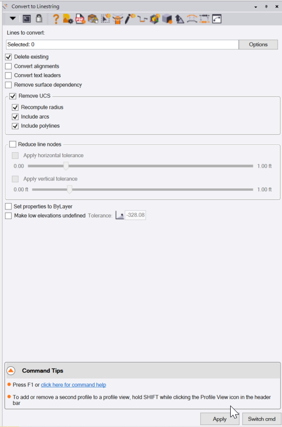
Lines to convert:
Select all of the CAD lines (CAD Lines, Polylines, 3D Polylines, Leader Lines etc.) that you wish to process using the command. Use the Options button to access the advanced selection modes including Advanced Select, Select by Layer, Select by Elevation etc.
Delete existing checkbox:
When checked, the source lines will be deleted once they have been converted into TBC linestrings. Note that this does not apply to Alignment objects, they are copied and the original alignment is left intact.
Convert alignments checkbox:
When checked, imported or hand entered alignments that have been selected can be converted to linestrings. Uncheck this checkbox if you do not want to convert alignments. Note that Arcs and symmetrical vertical curves in the source alignment can be matched to a linestring, however spirals, asymmetrical vertical curves and vertical arcs do not match with linestring object properties and require chording to approximate. Note also that linestrings do not have a Station Equation or Superelevation property so those elements of an alignment will be lost on conversion. Linestrings can have a Station property, this is created and the alignment start station is applied to the linestring that is created. You can review the station property of the linestring in the properties pane.
Convert Text Leaders checkbox:
When checked, text leader lines will also be converted to linestrings. it is common to not want to do this as text leaders are links between a text object and the location to which the text is referenced (TBC Smart Text), however sometimes it may be useful to carry out this process on imported CAD data.
Remove surface dependency checkbox:
If you select TBC contours that are created and dependent upon a surface model, you can check this checkbox to remove the dependency on the surface model. This can be used when generating data for Trimble field systems that leverage the TBC VCL format as a design data source, where you want to export the contours for a surface model but not with the surface and its dependent objects (points and lines that are members of the surface model). Note that only the contour lines become independent of the surface, if the contours have text labels, the labels and original contour objects (if you do not delete them) that remain after processing are still dependent objects of the surface model.
To avoid selecting the original contours or the text remaining after conversion, you can either delete the contour data or select the contours of the surface model in the Project Explorer and set their rebuild method to “Show Empty” while you are exporting data to the field. This will guarantee that you do not inadvertently select the original contour data which by default will select the surface and the surface members of the surface.
Remove UCS Section
Recompute radius checkbox:
A UCS (User Defined Coordinate System) is used by AutoCAD and Microstation to accommodate for the fact that they have no easy way to create curvilinear geometry in 3D within their CAD solutions. In TBC a linestring can include Arcs and Vertical Curves, and can also include any number of VPIs that define the 3D path of the line. In CAD systems, they can represent the curvilinear line in 2D only, so to create a 3D curvilinear segment they apply a UCS to the segment (typically arcs) so that it is drawn on a 3D plane. In addition when they tilt the arc using a plane, they often change the radius slightly so that it continues to fit the segments at either end of the arc. When we adjust out the UCS to return the lines to TBC linestrings without the UCS, we provide the ability to recompute the radius to take out the arc adjustments applied by the CAD system. Check this checkbox in most situations.
Include Arcs checkbox:
Check this checkbox if you want to remove UCS properties from Arc segments of lines
Include Polylines checkbox:
Check this checkbox if you want to remove UCS properties from Polylines and 3D Polylines.
Reduce line nodes checkbox:
When you import CAD data, especially data created by photogrammetric processing of drone data or from marine bathymetric surveys, many lines e.g. contour lines especially, can have hundreds or thousands of nodes that define the lines. When you incorporate those lines in surface models, each node (horizontal or vertical nodes) become a node in the surface, bloating the surface enormously. The options in this section allow you to apply a “tube filter” to the lines that will significantly reduce the number of nodes in the line without drastically changing the shape or path of the line.
A “Tube Filter” works by defining a horizontal and or vertical tolerance value. That value is effectively the radius of a tube that will be used to determine whether or not a node in a line should be kept or discarded. The tube is drawn initially between node 1 and node 2 of the line and is then projected forward in a straight line. Node 3 is then tested to see if it lies within the tube or not, if it lies inside the tube it replaces nde 2 in the filter and node 2 is discarded and the process is repeated for node 4. The process continues until the node being tested falls outside the volume of the tube. At that point the tube position and orientation is changed, to now be between the last retained node and the node that failed the filter test. The process starts again and repeats until the entire line has been filtered and adjusted.
The Tube filter will discard nodes of a line that fall on a straight line or straight grade (or close to it), and will keep nodes that alter the path of the line significantly (outside the tolerance of the tube filter). The tolerance value that you use to filter the data dictates the amount of data that is retained or discarded. You will find that even with small tolerances like 0.01’ you can eliminate large numbers of nodes from the selected lines. Small tolerances will discard less data than large tolerance values.
Apply horizontal tolerance checkbox:
When checked you can select the tolerance value that you wish to use using the slider control.
Apply vertical tolerance checkbox:
When checked you can select the tolerance value that you wish to use for he horizontal filter using the slider control. If left unchecked, no horizontal filter will be applied.
Apply vertical tolerance checkbox:
When checked you can select the tolerance value that you wish to use for the vertical filter using the slider control. If left unchecked, no vertical filter will be applied.
Set properties to ByLayer checkbox:
CAD data that is imported can have its color, linestyle and lineweight properties set to specific values or to ByLayer. In the event that the properties are not set to ByLayer, when this checkbox is checked, all lines that are processed using the command will have their properties changed to ByLayer automatically.
Make low elevations undefined checkbox:
When you import CAD files, AutoCAD and MicroStation both use Elevation 0 as their equivalent of TBC undefined elevation (Elevation 0 is a real elevation in TBC). Also you will often find a lot of CA objects have elevations other than 0 that are not in the elevation range of the project i.e. the project is at elevation ~2500, but there are lines at elevation ~600. When you are processing lines using this command, you can set objects that have elevations below a defined value to undefined elevation, so that when they are later used in surface models, you will not have elevation issues to resolve. When checked, enter the Tolerance value below which all elevations will be set to ? i.e. undefined. in the example above use elevation ~700 as the tolerance (this is a long way below 2500 and above the elevations that you know are incorrect).
Apply:
Executes the command with the selected data and selected settings and prepares itself for another process execution.
Switch cmd
The Switch cmd button provides a list of currently running Smart Suite commands. You can switch command to one of those listed, or you can select Close to close the current command or Close All to close all currently running commands. The Switch cmd function can also be activated by te ESC key on your keyboard, this will pop up the Switch cmd list right by your current cursor position. If you wish to close the command you are running you can press ESC ESC on your keyboard to close the command.
Header Bar Commands
In the header of the command dialog you will find icons that provide shortcut links to other commands that you may find useful while running the Convert to Linestring command. The Header Bar icons act as toggle switches to switch command to the one selected if it is already running, or they will open a command if it is not already running. Header Bar commands in Convert to Linestring include the following
- Help (this document)
- RPS Settings
- PDF Manager
- CAD Cleanup
- Smart Select
- Smart Draw
- Smart Edit
- Smart Elevate
- Smart Model
- Volumes Manager
- Explode Lines
- Reverse Line
- Profile Viewer
Command Tips
The command tips area provides a link to the command help documentation (this document). In addition it provides tips and other useful information that you may find helpful while running the command. If there are any Hot Keys applicable to the command, there will also be listed here.
Use Case Videos (Nov 2021 Update)
The following videos show the use of the Convert to Linestring command in a work process context for removing the surface dependency of contours from a surface model and to filter / reduce the line vertices in the resulting linework.
Feedback and Enhancement Requests
If you would like to provide feedback on the use of the Convert to Linestring command or to request enhancements or improvements to the command please click Reply below.