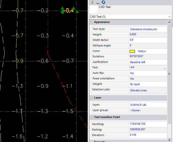
In todays v2026.2 release there is an Elevate Text by Text command in Smart Elevate - that allows you to set the elevation of Text labels to the Text Value of the label itself. That will solve the first part of the problem.
The second part of the problem is how do you than modify an existing surface model with these differences at each point location - that will entail creating a copy of the points created from the text labels and elevating them from the surface model (Smart Elevate, Simple Mode, From Surface), I would then report both sets of points using Point detail Report to excel as two reports, sort them by N and E so that they are on the same row as each other and then do a math function in Excel to compute the new Z from Surface Z plus Cut / Fill Value.
Or I would write an AI Script and get it deployed on Cloud Services because that should be easy
Here is the CHATGPT Script I wrote
Take this surface provided in LandXML format, and this CAD File provided in DXF format. For each of the text labels in the DXF file, compute a 3D point at the Northing, Easting insertion point of the text, and set the elevation to be the surface elevation at that lovcation +/- the elevation adjustment derived from the text label itself. ie if the Text Label says -0.5 then take the surface elevation at that point and subtract 0.5 from the surface elevation to derive the point elevation. Write out the computed Points as CAD Points in DXF R12 Format, along wiyth a text label at each point that shows the following text items in the label Elevation Adjustment (EL ADJ: Value) derived from the text label, Surface Elevation (EL S: Value) derived from the surface at the label insert point, Adjusted Point Elevation (EL PT: Value)
I then had to qualify that the LandXML is in Metric Units (a new Trimble Standard) and the DXF was in US Survey Foot Units to clarify that the two files were in different units.
I also asked it to write out the DXF labels as three labels at each point using this clarifier
Can you reoutput the DXF using Multiline Text or three text labels for the results at each point, so that the text labels are to the right of the point, one at the same N as the point, one abvbiove and one below with no overwrite of the labels.
Here are my Test Input Files - generated by TBC
Surface Model.xml (374.1 KB)
CF Labels.dxf (29.1 KB)
Here is the output file it generated
Computed_Adjusted_Points_Three_Labels_R12.dxf (46.2 KB)
And an CSV / Excel Report that it generated for the analysis
Computed_Adjusted_Points.csv (8.7 KB)
Having written this script, I can have ChatGPT generate the code for me to deploy on Cloud Services for the benefit of running this again in the future
Alan