RPS Settings - Smart Model Settings

Smart Model Command documentation - Click Here
Smart Model - Cut Fill Maps Command documentation - Click Here
Command Licensing and Default Menu Location
- The RPS Settings command is part of the RPS Core Tools
- The command is located on the RPS Support macros menu ribbon
- The command is located in the Core menu group
Command Description
RPS Settings provides access to all of the centralized settings for all RPS Command Library tools. The command access the .rps settings file for each command that resides in the RPS Settings folder (look in RPS Settings - File Locations to determine the location of this folder on your PC).
RPS Settings are 100% detached from your TBC installation and will always survive a TBC update or reinstallation process. Like any other valuable data, you should backup you RPS Settings folder to protect your time investment used to develop the master settings for your TBC installation.
The Smart Model command has two settings files, one that contains the current default settings installed by the Smart Model command, and one containing your personal custom settings. Your personal custom settings include Surface Groups, Surface Styles, Cut Fill Map Styles etc.
The default file is called RPSSmartModelSettings.rps
The custom file is called RPSSmartModelCustomSettings.rps
If you wish to share your custom settings with others, simply share the custom .rps file with them and have them place the file in their RPS Settings folder on their computer.
Command Interface Description
The RPS Settings - Smart Model Settings tab dialog looks as follows
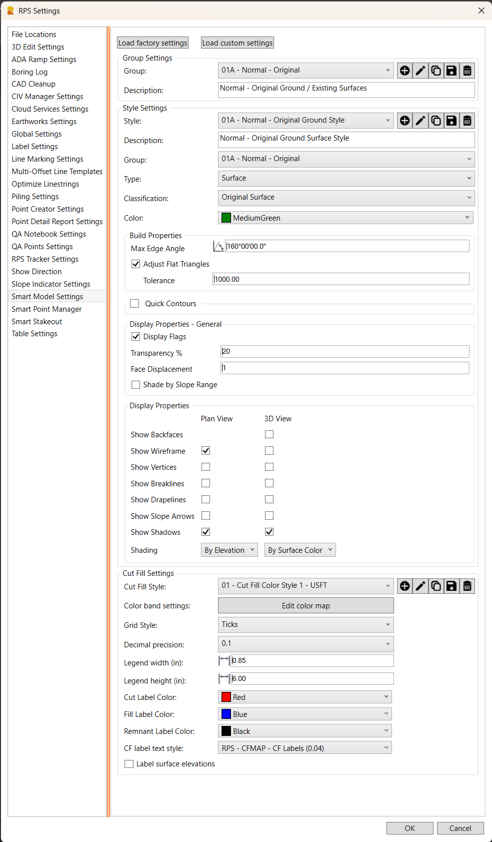
RPS Settings - Load Factory Settings / Load Custom Settings Buttons
The Smart Model command is installed with a set of "factory settings for Surface Groups, Surface Styles, and Cut Fill Map Styles.
These will be stored in a file called RPSSmartModelSettings.rps which is located in your RPS Settings folder.
The factory settings are stored within the command itself, and can be restored to the original setup at any time using the Load Factory Settings button. This will reset all Styles and Groups to the defaults, but will leave your custom settings alone because they are stored in a second settings file.
Your custom settings and styles (Surface Groups, Surface Styles, Cut Fill Map Styles) are stored in the settings file called RPSSmartModelCustomSettings.rps, also located in the RPS Settings folder.
You can find your RPS Settings folder location by looking in RPS Settings - File Locations.
RPS Settings - Surface Groups
Surface Groups are managed, created and edited using the RPS Settings - Smart Model Settings command. You can access this function using RPS Settings icon in the header bar of the smart model command, or by clicking the Styles / Groups button in the Surface Properties - Parameters Tab of the Smart Model command.

You can use the buttons to the right of the Group selector to
- Create a new surface group
- Edit the name of a surface group
- Copy a surface group
- Save a surface group
- Delete a surface group
A surface group has a name and a description field only. The description field is there to provide additional details not conveyed by the surface group name. It is an optional field for completion.
RPS Settings - Surface Styles
Surface Styles are managed, created and edited using the RPS Settings - Smart Model Settings command. You can access this function using RPS Settings icon in the header bar of the smart model command, or by clicking the Styles / Groups button in the Surface Properties - Parameters Tab of the Smart Model command.

The surface style comprises settings that control the display properties of a surface in Plan and 3D Views, as well as some of the properties that are used to control the way the surface is created / built and also the need to generate quick contours for the surface etc.
The goal of a surface style is to give you a one click process to change the way that the surface is displayed in plan and 3D views, depending on what you are doing, or what type of surface you are working with.
Style
Select the style that you wish to review or edit. You can also use the buttons to the right of the style selector to
- Create a new style
- Edit the name of a style
- Copy a style
- Save a style
- Delete a style
Description
A style can have a description. The description field is optional and is used to provide more detail about the style that is not conveyed by the style name only.
Group
A style can define the default Surface Group that will be assigned to the surfaces given the style. When you change a surface from one style to another, this will cause the surface to be moved from one group to another also. For example if you move a surface into style 99C - Surface Under Review Style, this will cause the surface to also move to the surface group 99C - Under Review.
Type
The surface type is a defined list of surface types supported by TBC. Surfaces used by the TBC Takeoff workflow are all hard coded and cannot be changed. While all surface types are listed here, Surface and Takeoff / Layer Surface are the only two that can be user selected, the others are automatically assigned when you create those surface types outside of the Smart Model command.
Classification
The classification of a surface provides hierarchy context to the surface that is used when carrying out volume computations, that ensures that the Cut and Fill values determined by the volume calculations are the right way around. i.e. Original Surface comes before Work In Progress, comes before As Bult comes before Design when it comes to volume calculations. We recommend that you always classify surfaces in TBC, as we will be using the classification more and more over the coming months.
The classification is also supplemented by the Date and Time assigned to a surface model when it is created. The Date and Time is used to determine the order of surfaces in volume calculations when two surfaces of the same classification are selected i.e. Work In Progress Surface 1 and Work In Progress Surface 2. This further ensures that your volume calculations will be determined the right way around for Cut and Fill purposes.
Color
This is the default surface color for surfaces assigned this Surface Style. The surface color is used for the solid surface color that renders the triangles of the surface when it displays “By Surface Color”. It is also used for the lines that represent the surface in surface slicer and profile views.
Note that when you add PDF images or ortho photos to a surface as surface members, they will override the surface color for display in plan and 3D views when the surface is set to display “By Surface Color”.
Build Properties
There are some surface build properties that we consider to be unique to each surface model e.g. maximum edge length setting, and there are others that we believe can be set as defaults using the style e.g. Max edge angle and adjust flat triangles etc. Those that are defined using the style are input here.
Max Edge Angle
In the same way that Max Edge Distance controls the length of the sides of the triangles of a surface model, the Max Edge Angle controls the maximum angle of any angle of the triangles. This is used to limit the formation of long skinny triangles along the edges of the surface model. We recommend a default value of e.g. 160 degrees.
Adjust Flat Triangles Checkbox
When you build surfaces from contours especially but also when building highways models or stockpile models, it is often important that you enable the Adjust Flat Triangles setting and define a suitable tolerance for the flat triangle adjustment. Depending on what you are working with, e.g. Contours, then the tolerance is acceptable at e.g. 0.5’ or 0.5m. If you are working with 3D variable height linework, then the tolerance value needs to be greater than the maximum elevation variation that you will find on the lines, i.e. if the base of a stockpile has an elevation range of 99.0 to 108.0 then you will need a tolerance of 9.1 or 10 to force triangulation between lines i.e. up and down the slope rather than allow triangulation between 3 points on the same line which can create model flat spots. In most cases, setting Adjust Flat Triangles to enabled, and setting the Tolerance to e.g. 1000 will provide a good solution in most modeling scenarios. In some cases however you may want to set the tolerance e.g. to a small value like 0.5 to achieve the most desirable triangulation.
The original intent of this control was to force triangulation to form between contours, rather than allowing a triangle to form between 3 points on the same contour, thereby creating a flat spot. To achieve this goal a tolerance of 1.0 is adequate because the range of elevations on a single contour is less than 1.0’.
Quick Contours Checkbox and Quick Contour Settings
If you wish the surface style to trigger the formation of quick contours on the surface, enable this checkbox. When enabled, enter the settings required for the quick contours as follows.

Name
Name the contour lines e.g. Contour
Interval
Set the minor contour interval e.g. 0.1’
Frequency
Set the frequency of the major contours e.g. 5 for every 5th contour
Major Contours Color
Select the color for the major contours
Minor Contours Color
Select the color for the minor contours
Display Properties - General
In this section of the style, you will define general display properties for the surface including
Display Flags checkbox
When enabled, surface flags that indicate locations on the surface where there are 2 or more sources of elevation (points, lines etc.) that have different elevation values at the same exact location. This is an illegal state for a surface model, so TBC will always use the lowest of the 3D locations and place a yellow flag on the higher locations to warn you of the potential issue with your surface. You can review the magnitude of the error using the Flags Pane accessed from the “toggle button icons” at the base of your screen in TBC.
![]()
Transparency %
Set the desired default transparency for the surface model. 0% is opaque, 100% is fully transparent. Transparency allows you to see through the surface to objects that reside below the surface in both the Plan and 3D views.
Face Displacement
When you have two or more surfaces that have areas of identical elevation, the graphical views will bleed one surface into another creating a poor graphical view. You can set the default face displacement for a surface so that it will take a higher or lower priority graphically than other surfaces.
Without Face Displacement

With Face Displacement

In this example, the purple surface was set to face displacement = 1 vs the green surface has face displacement = 2. The lower the face displacement number, the higher the display priority becomes. The range goes from -8 to +8, -8 being the highest priority and +8 being the lowest priority.
Shade by Slope Range
When enabled, enter the slope range for the triangle faces that you want to shade in. There are a number of applications or model building QA processes where shading a surface to check that triangles are falling within a defined slope range. Examples include solar farm projects, if the terrain exceeds a certain maximum slope, the terrain will need to be reshaped to make the slopes shallower, so by shading the surface using a defined slope range allows you to see quickly where the surface has slopes that are acceptable e.g. between 0 and 15%, and where the slopes exceed the maximum slope e.g. 15% to 1000%.
Note: RPS Cloud Services offers a more comprehensive solution to this requirement, it provides the ability to shade North and South or East and West facing triangles to be shaded with different colors as well as shading each slope range band with different shades of the same color.
Check the checkbox and then enter the min / max slope values. The surface model will then shade those triangles that fall within the range and leave the faces outside the range unshaded.
![]()
Display Properties
In this section of the style, you will define the primary display properties for the surface model for the Plan and 3D views respectively. The settings include
Show Backfaces (3D View Only)
A surface by default renders the top side of the surface so that when viewed from above the surface appears solid (+/- transparency). If viewed from below, the triangles are unshaded, and appear white or black depending on your selected graphics pane color (black or white). If you wish to render the back faces with the surface coloration also, check the checkbox in the 3D column.
Show Wireframe (Plan and 3D View)
The wireframe is the triangular mesh of 3D faces that represents the surface. Check the checkbox to be able to see the wireframe in the Plan and or 3D Views.
Show Vertices (Plan and 3D View)
The vertices are the 3D nodes of the surface model. These will be displayed as a small * at each node when enabled in the Plan or 3D Views.
Show Breaklines (Plan and 3D View)
When you add 3D lines to the surface model, the lines will be used as breaklines in the surface model. The breaklines force the triangles to follow the breakline, such that no triangle side crosses the breakline. When viewing the surface model, if you turn off all CAD object visibility, and if the Breaklines is enabled here, then the 3D lines that were used in the model will be visible as surface breaklines in Plan and or 3D Views.
Show Drapelines (Plan and 3D View)
When you assign site improvements, topsoil strip, topsoil respread or surface textures to a surface model, the boundaries of those areas are formed in the surface model as drapelines. The drapelines will be visible when this is enabled for a surface in Plan or 3D Views.
Show Slope Arrows (Plan and 3D View)
The slope arrows indicate the direction of slope in each triangle face of a surface model. When enabled, you will see an arrow in each triangle if the triangle has slope, or a diamond if the triangle is perfectly flat. The slope arrows indicate the direction of water flow on a surface. Note that Arrow size is defined in Project Settings - Computations - Surface - Slope Arrow Length.
Show Shadows (Plan and 3D View)
When a surface model is built, linestrings that have either the sharp or sharp and texture boundary property for surface sharpness, will form hard shadow transitions along those lines in the surface. If the linestring property is set to soft, or where triangles have no breaklines, only points, then the surface areas will be shaded in a similar way, providing less shadow - thereby representing the surface as smoother or sharper accordingly. Sharp breaklines like those found along retaining walls, foundation trenches, and curb and gutter lines, will display better when there are shadows enabled.
Shading (Plan and 3D View)
The surface can be shaded in one of the following ways
- None - surface area will be unshaded
- By Surface Color - surface area will be shaded in the surface color or if images are draped on the surface in the colors of the image or PDF file page.
- By Elevation - surface area will be shaded using color bands representing different elevation ranges.
- By Material - when surface textures or site improvements have been applied to a surface, the texture color or texture image, or site improvement color will be used to render the different areas of the surface.
Cut Fill Settings
See the RPS Smart Model - Cut Fill Map command documentation for full details of the RPS Settings functions for Cut Fill Maps. Click Here for full details.
OK
Closes RPS Settings and saves your changes.
Cancel
Closes RPS Settings without saving your changes.
Video Demonstrations
See the video presentations with the Smart Model or Smart Model - Cut Fill Map documentation pages.
Feedback and Enhancement Requests
If you would like to provide feedback on the use of the RPS Settings - Smart Model command or to request enhancements or improvements to the command please click Reply below.