Smart Model

Command Licensing and Default Menu Location
- The Smart Model command is part of the RPS All Tools Command Library and one of the key commands of the RPS Smart Suite package
- The command is located on the Modeling and Smart Suite macros menu ribbon
- The command is located in the Surface menu group (Modeling Menu) or the Model menu group (Smart Suite Menu)
Command Description
Provides the ability to create and manage your TBC surfaces and Cut / Fill Maps. The command integrates TBC capabilities including the surface creation, adding / removing surface members, trimming surface edges, adding surface edge breaklines and boundaries into a single seamless process. Surfaces and Cut Fill Maps generate reports that are linked to the surface selected, so that you can see and report all surface properties and all volumes calculated directly.
Documentation Links
Smart Model - Cut Fill Maps Command documentation - Click Here
RPS Settings - Smart Model documentation - Click Here
Video Demonstration - Smart Model - Surface Models
Command Release History
- July 7 2025 - Version 2 with Cut Fill Maps and other capabilities
- April 1 2025 - Version 1 released
Command Interface Description
The Smart Model command dialog looks as follows

Surface Type Filter
In TBC there are a number of surface types available to you depending on the work type that you are doing. The Surface Type filters provide the ability to reduce the number of surfaces and surface groups that are displayed in the surface Manager window (see below).

Surfaces have been logically grouped into three main groups, those being
- Normal Surfaces
- Takeoff Surfaces
- Other Surfaces
Normal Surfaces include standard surface models, planar surface models, corridor surface models, trench surface models and difference or cut / fill models.
Takeoff Surfaces include all of the surfaces created using the Takeoff work processes including Original ground, Finished design, topsoil stripped and topsoil respread removed surfaces, strata surfaces (rock, soil etc.), subgrade adjusted and demolition surfaces, and overexcavation surfaces.
Other Surfaces are the specialist surface types including composite surfaces, projection surfaces, radial surfaces and tunnel surfaces.
In the Filter area of the command dialog, you can switch the filters on / off using the checkboxes beside each surface type or at the Surface Type group level.
When a surface type or types are disabled in the filter, they cannot be displayed in the Surface manager window, or in the plan or 3D graphics pane.
Note:
Because Smart Model cannot control the overall behavior of TBC, it is possible still to control surface visibility using the view filter manager. While Smart Model is running and is the active command, or when it is started up, it controls the graphics and will override the view filter manager automatically provided that the View Filter in use is an unlocked view filter (like MyFilter) i.e. locked view filters (All or other locked view filters) override Smart Model and control object / layer visibility the current view.
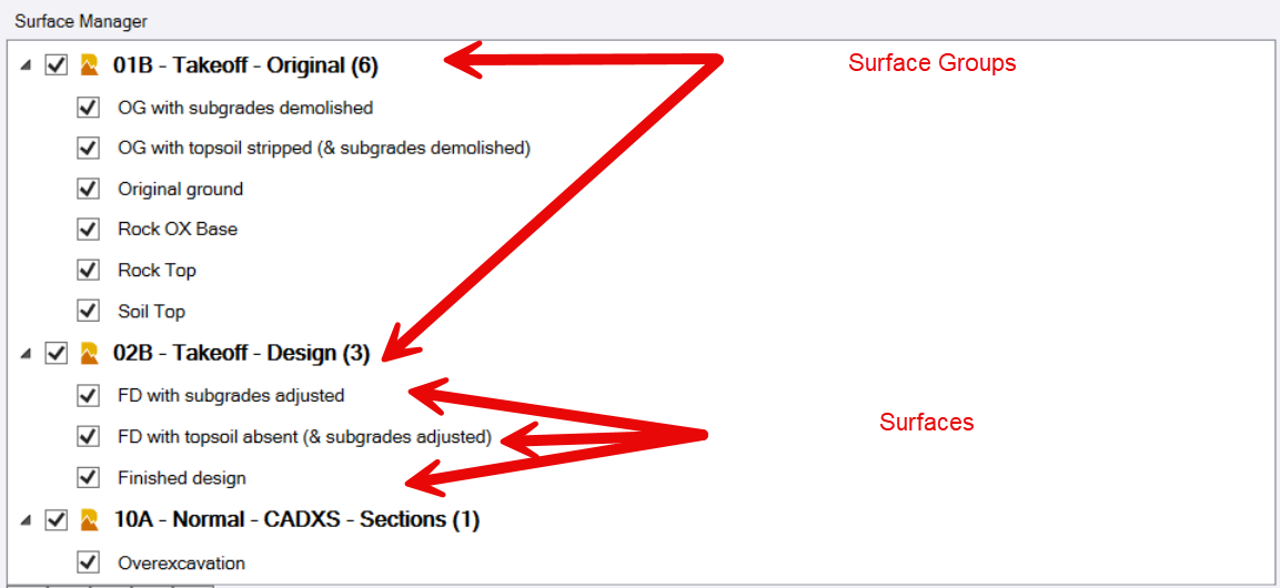
Surface Manager
The Surface manager window will display surface groups and surfaces that are enabled in the surface type filter above. You can turn surfaces on and off at a surface or surface group level within the surface manager, by checking or unchecking the checkbox next to the surface model or surface group.
You can increase or decrease the height of the surface manager window by right clicking your mouse in the window and dragging the mouse up or down in the window.
If you click on a surface in the surface manager, that surface is activated and you can control the surface parameters, members, edits, boundaries etc. in the section below. You can also review surface information or in the Cut / Fill type surfaces you can review the volumes computed and other related information in the results pane of the dialog.
When a surface is activated, you can right click on the surface name and select one of the following options
- Properties - opens the properties pane for the selected surface)
- Reassign Group - moves a surface from one group in the surface manager tree to another group in the tree (or to a group that is not currently in the tree view)
- Delete Surface - Deletes the selected surface
- Duplicate TIN surface - Creates a copy of the TIN surface without any dependent object relationships - suitable for machine operations
- Capture view to clipboard - Copies the active view to the clipboard so that it can be pasted onto a drawing sheet in sheet view using RPS Paste
- View only this surface - Switches off all surfaces except the selected surface
- View all surfaces - Switches all surface models on
Properties
Will trigger the display of the surfaces properties in the TBC properties pane. If the properties pane is not open, it will open on this request.
Note that the Results pane of the Smart Model command will also provide a detailed list of surface properties or cut fill map properties when the surface is selected in the surface manager window. The parameters tab of the section below, will also show the key parameters of the surface properties e.g. Surface Group, Surface Style, Rebuild Methods etc.
Reassign Group
Provides the ability to select a surface group from a list of surface group and moves the selected surface into that group of the surface manager tree. You can also drag and drop a surface from one group to another in the surface manager tree.
Delete Surface
Will delete the surface from the TBC project file, it will then also disappear from the surface manager window.
Duplicate TIN surface
Will create a simple TIN model copy of the selected surface that has no dependent objects. The surface created is well suited for use in machine control or surveying systems and can be selected and exported as a VCL, TTM, SVD/SVL, or DSZ file for use in Trimble construction systems (Siteworks, Earthworks, GCS900, SCS900 etc.)
Capture view to clipboard
This captures the currently active view e.g. 3D View or plan view to the clipboard as an image. The image can then be pasted into the Plan or a Sheet view for drawing purposes. Note that the size of the graphics window and the resolution of the screen the window is on, dictates the resolution of the image that is captured. Alternatively you can use the Windows Snipping tool, Snagit or Sharex for example as alternative screen capture tools that also place the image on the clipboard so that you can use RPS Paste to place the image in the desired location.
View only this surface
This switches off all of the surfaces except the one that you have selected in the currently active view, so that you can review just the one surface model on screen.
View all surfaces
This switches on all surfaces in the currently active view.
Note: Currently the view controls do not have a total grip on multi window TBC projects e.g. multiple plan and 3D views where each view can have a different Locked / Unlocked view filter - we still have some work there to improve the way Smart Model interacts with multiple views and also multiple locked or unlocked view filters.
Surface Groups
Surface Groups are defined in RPS Settings and are stored in an RPS Settings file which is not a part of the TBC project. The same Surface Groups and Surface Styles can be used from project to project - see RPS Settings - Surface Groups and RPS Settings - Surface Styles below for more details.
A number of standard Surface Groups have been defined for you already, you can rename them, or change their definitions as you see fit, or create new ones as needed for your desired project structure. Surface groups are simply a way to group surfaces together for better / faster visibility controls, and better organization, making them easier to locate and manage on larger projects.
Examples of how to group surfaces could include any of the following methods.
- Group by surface type i.e. Original Ground, Finished Design, Work In Progress, As Builts, Utility Trench etc.
- Group by project phase i.e. Phase 1 surfaces, Phase 2 surfaces, Phase 3 surfaces etc.
- Group by surface use case i.e. Main Line surfaces, Ramp Surfaces, Pond Surfaces etc.
- Group by surface type i.e. Normal Surfaces, Cut Fill Maps, Takeoff Surfaces etc.
- Group by revision i.e. Rev 1 Surfaces, Rev 2 Surfaces, Rev 3 Surfaces etc.
There is some degree of loose coupling applied by the Smart Model command between surface type, surface classification, surface group and surface style. These are mostly user definable and can be overridden by the user as needed. Takeoff surfaces are hard coded to match the default behavior of TBC Takeoff processes so that they are 100% consistent.
A surface can be moved between surface groups at any time, so you can use surface groups to hold surfaces in one group while you are working with them, and then move them to a different group when they are completed. Surface groups have been provided to store the simple TIN models for machine control, for surfaces under review as a start for you to work with as you work out how best to utilize the tools within the command.
See RPS Settings - Surface Groups below for mor details.
Surface Styles
Surface Styles are defined in RPS Settings and are stored in an RPS Settings file which is not a part of the TBC project. The same Surface Groups and Surface Styles can be used from project to project - see RPS Settings - Surface Groups and RPS Settings - Surface Styles below for more details.
A number of standard Surface Styles have been defined for you already, you can rename them or change them as you see fit or create new ones as needed for your desired project structure. Surface styles are a simple and fast way to set the surface properties for display in Plan or 3D views, and to set the default surface build properties like max edge angle, adjust flat triangles etc. and to enable / disable the automated creation of quick contours. Some properties of a surface like Maximum Edge Length are not tied to the surface style, so that they can be controlled at the individual surface level.
A surface style can be changed at any time, this will trigger a change in the display of the surface in the plan and 3D view and an update to the surfaces properties. When you change a surface style, the selected style does not automatically override all of the current display properties, to set those, you will click on the “red flag” button that appears to the right of the surface style selector when you change the surface style.

To change a surface style, pull down the list of available surface styles and select the desired style, then click Save to implement the change. When the change has been implemented, the red flag button will appear, click that to make the display changes to the newly selected style.
The red flag button indicates that the current surface properties do not match the selected surface style, clicking the button forces the surface properties to change to those defined by the surface style, leaving the flag button, leaves the properties as they are for now but warns you that they are not matching the selected style.
If a surface style includes the creation of quick contours, the quick contours will be generated and placed on a layer with the name “Surface Name - Contours” and will be placed in a Layer Group called 99 - SURFACE CONTOURS.
When you change a surface style from one that has contours to one that doesn’t have contours, the surface contours, the associated layer and or the associated layer group will be automatically removed or added as needed.
See RPS Settings - Surface Styles below for more details.
Surface Manager Button Controls
Below the surface manager window you will see the bank of control buttons as follows
![]()
The buttons control the following functions from left to right
 Create a new surface
 Delete the selected surface
 Refresh the Surface Manager window
 Expand all surface groups
 Collapse all surface groups
Surface Properties Dialog Area
The surface properties area of the dialog looks as follows, and is used to either create new surfaces or edit existing surfaces.

When you select a surface in the surface manager window, this area of the dialog is populated with the information relating to the selected surface.
When you click the ![]() button to create a new surface, this dialog area becomes the area that you define the parameters and members etc., of the new surface.
button to create a new surface, this dialog area becomes the area that you define the parameters and members etc., of the new surface.
The dialog area is broken into a set of tabs, each tab represents a process step in the creation of a new surface, or provides the ability to review the parameters of the selected surface. The process steps are defined in a work flow order (when the command dialog pane is wide enough to display the steps in a single line from left to right as shown above).
To widen the command pane, hover your mouse over the left edge of the dialog, and when the pane widening icon appears, click your left mouse button and drag the edge to the left or right to widen the pane.
The process of building a new surface requires the following key steps
Parameters
In this tab you will create the main properties of the surface including
- Type - this is the surface type, options include Surface (Normal TIN), Takeoff / Layer Surface and Planar Surface. Note that Takeoff / Layer surfaces are unique in that they are created automatically if you have “categorized” layers for takeoff i.e. for Original ground or Finished design surface. The other Takeoff surfaces include the topsoil (strip / respread), subgrade (demolition / subgrade), strata (soil / rock) and overexcavation surfaces and are created by the Takeoff process and cannot be created here.
- Name - name the surface that you are creating.
- Style - set the display style for the surface that you are creating. Surface styles are defined in RPS Settings, you can access RPS Settings from the header bar commands or by clicking the Styles / Groups button.
- Group - set the surface group for the surface that you are creating. Surface groups are defined in RPS Settings, you can access RPS Settings from the header bar commands or by clicking the Styles / Groups button.
- Classification - classify the surface you are creating. Surface classification ensures that cut / fill quantities are always determined the right way round and it is good practice to assign the classification here as you create the surface.
- Date / Time - the Date and Time further assist the determination of Cut / Fill when you run a volume calculation between two surfaces that have the same classification e.g. between two work in progress surfaces, date and time then determines which file is earlier or later in sequence to determine the cut or fill values.
- Color - the color of the surface is defined by the selected surface style and is displayed here as a reference only.
- Rebuild method - set the rebuild method for the surface that you are working on, Auto will rebuild non takeoff surfaces automatically on any surface member change, By User will rebuild surfaces on request only, and Show Empty will retain the surface container and the selected members, but will prohibit formation / display of the surface until it is reset to Auto or By User. Use the By User when you want to make a number of surface changes before rebuilding the surface when you are ready to do so. Use the Show Empty to e.g. temporarily disable the rebuilding of e.g. Cut Fill Maps when you are making changes to the source surface models to save rebuild time after each set of edits.
- Max Edge Length - this is not defined as a part of the surface style, you define it here for each surface that you create. The setting is somewhat unique to each surface in a project. This limits the length of triangle sides in the surface, especially around the edges of the surface, to mitigate the amount of surface edge trimming that may be required.

In this step you have defined the container for the surface, the surface members will be selected in the following step of the process. Surface members can be selected in a couple of different ways, which is why it is separated out into a different process step.
Save
When you have entered all of the surface parameters in the Parameters tab of the Surface Properties dialog area, click the Save button to create the surface and refresh the Surface Manager prior to the subsequent steps of the surface creation process,
Refresh
The Refresh button will compare the parameters of the surface as they are currently defined against the properties of the surface as they are defined (in the properties pane). If there are differences between the two, the red flag button will appear to the right of the Style selector, allowing you a single click to match the properties to the currently defined surface parameters..
Properties
The Properties button will trigger the display of the surface properties in the properties pane.
Selecting Surface Members
Depending on the type of surface being created (Normal Surface or Takeoff / Layer Surface) the options will vary as shown below. Note that for Normal Surfaces, Smart Model allows you to select members using Layer Group, this is a non standard TBC function, and collates the members for a surface from 3D objects located on layers in the selected layer group(s). Note that because this is not a native TBC surface type, you have to use Smart Model to rebuild the surface if you
- Add new layers and 3D objects to the Layer Group after the surface has been created.
- Add new TBC objects to the layers of a Layer Group after the surface has been created.
Categorize Layers - Takeoff / Layer Surfaces Only
This option will be available only when creating Takeoff Surfaces i.e. Original ground or Finished design surfaces only.
These surfaces are created using layers of data that have been categorized as Original or Design surface related. Typically, the Categorization of layers can be managed by your Project Template, and modified for each project to allow for data variations encountered. In Smart Model you can now do the layer selection and categorization for Original ground and Finished design surfaces for Takeoff within this process step.
If your project template has layers already categorized for Takeoff, then they will be detected and displayed in this tab for review as shown below.

Layer Groups
If the categorization of layers collates layers from different layer groups, this will display Mixed to indicate that layers from more than one Layer Group are being used to make the surface. If the layers come from a single layer group, the layer group will be displayed here.
When building a surface from scratch (no pre categorization of layers), then selecting a layer group from the list, will display all of the layers from that layer group in the section below.
Layer List
The list of layers will be populated. For each layer in the list, you can select whether lines on the layers will act as
- Surface Boundary - either an External or Interior Boundary line (not this will create a surface area limited by an external boundary, and or holes in the surface (interior boundary) or islands in the surface (several external boundaries) etc.
- Contains SIs - SI = Site Improvement. This means that lines on the layer will act as a boundary for the placement of Site Improvements / Materials that will be used to create demolition adjustments (original ground) or subgrade adjustments (Finished design).
- Site Improvement - when the Contains SIs check box is enabled, you can optionally select a Site Improvement that will be automatically applied to all closed areas defined by lines on the selected layer. This would be e.g. used for subdivisions where there may be many building pads on a layer that all have the same site improvement treatment. Typically layers that contain open lines, or data that only represents one or two areas of the same type, or areas that have different site improvement treatment, will not be automatically assigned a site improvement here, you will do those manually in a later takeoff step.
Apply Button
When you have filled out the categorization for the selected layers, click Apply to activate the changes for the selected takeoff surface.
Refresh Button
You can refresh this list if you change anything via the categorize layers command so that they match up correctly. Click the Refresh button to update the table.
MSI Library Button
You can access the MSI (Materials and Site Improvement Library), to define or modify materials or site improvements that you are using. Click the MSI Library button.
New Layer Button
If you wish to create a new layer and set the layer categorization and site improvement properties, click the New Layer button.
Layer Groups - Normal Surfaces Only
TBC does not natively support the creation of Normal Surfaces using members selected using Layer Group(s). It is clear however that many users create layers in a layer group, often with the intent of using 3D objects on layers in that layer group to create a surface model. For this reason, we have created this method of surface creation. We are still improving the method, but it is already highly functional in v1.0 of the command.
In this method, you can select a Layer Group, on doing so the layers of that layer group will be listed in a table form below the Layer Group selector.

Within the layer table, you can check the boxes associated with each layer to indicate that 3D objects on the layer can be used to
- Create a surface boundary or boundaries. A surface can have one or more surface boundaries that constrain where triangles can be formed. A boundary can act as an external boundary (creates an island) or an internal boundary (creates a hole in the surface e.g. for a wetland area or a protected tree copse or similar). You can have any number of external boundaries that will create multiple islands in the surface. You can have any number of internal boundaries within each external boundary that will create one or more holes in the surface islands. While it is possible to have boundaries inside holes etc. that is less common, but if encountered they will become islands in the holes and this Island - Hole - Island - Hole sequence will repeat if boundaries are found inside other boundaries. If you create multiple closed lines on a layer in a selected layer group, then they will behave in this manner to constrain the surface. Note that surface boundaries can be 2D or 3D lines, and can be polylines or linestrings.
- Create a Site Improvement boundary (SIs). This will convert any 3D line found on a layer tagged as containing SIs into a linestring. It will also automatically change the Surface Sharpness property of the linestring to Sharp and Texture Boundary, so that the line will act as a boundary for the application of site improvements or surface textures using the Apply Surface Site Improvement or Add Surface Texture commands. These commands leverage the MSI (Materials and Site Improvement) Manager command for the colors to be assigned and the Site Improvements that are to be applied. Areas that have these SI treatments, can then be used to create subgrade surfaces using the Create Subgrade Surface command.
Add Group Button
Click this button to add the selected layer group to the surface and update the lines on the selected and tagged layers with their Sharp and Texture Boundary property, and add the selected lines as surface boundaries.
Remove Group Button
Click this button to remove the selected layer group from the surface. This can be used e.g. when you move from a Rev 1 surface to a rev 2 surface model for example, where the Rev 2 data is in a different layer group.
Layers Manager Button
Click this button to open the TBC Layer Manager window. This allows you to create, rename, delete or change the properties of selected layers.
Members - Normal or Takeoff Surfaces
All surface models are made up of members. Takeoff surfaces get their initial members at least through the categorization of layers as e.g. Original ground or Finished design. Normal surfaces get their initial members through either the selection of members graphically or through the Layer Group method defined above. However all surfaces can have additional members also that maybe were not defined by categorization, layer groups or from initial graphical selections. Some object types e.g. TIN models, PDF or Aerial Images / Ortho Photos, Point Clouds, Corridor Surfaces do not have layers and can only be added to a surface model as a surface member.
The Members tab provides the ability to add / remove members to / from a surface model, and the ability to add / remove PDF images / Ortho Photos from a surface model (this drapes the image over the surface model for visualization purposes).

Surface Members
Click in this field and then graphically select or use the Options button for advanced selection methods to select members for addition or removal from the selected surface model.
Add Members Button
Click the Add Members Button to add the selected objects to the surface model
Remove Members Button
Click the Remove Members Button to remove the selected objects from the surface model
Drape Images
The table shows all of the images / pdf pages that have been imported and georeferenced in the project. If you check the check box associated with any image, it will be added to the surface as a surface member, and will be used to colorize the surface when it is displayed using Surface Color display style in the Plan or 3D view.
Check the check boxes and then click Build / rebuild surface to add the images to the surface model.
Uncheck the check boxes and then click Build / Rebuild Surface to remove the images from the surface model.
Alignment Surface Check Box
Currently a placeholder in the dialog - Not fully implemented at this point. This will be fully implemented in the next update to the command. (Comment Dated Apr 2025)
Trim Edge
When you build a surface, the Maximum Edge Length parameter set in the parameters tab, controls the formation of the surface model in terms of the maximum edge length that a triangle can have.
Note that regardless of this setting, every 3D point or node of any line etc. selected for a surface model, has to be connected by at least one triangle, and that single triangle can exceed the maximum edge length setting.
For nearly all surface models, you will need to set this value somewhere higher than absolutely necessary for each pair of points or nodes, but set it not so large that the surface will create really large triangles where they are unnecessary / unwanted.
Whatever value you set here, will never be 100% correct, and you will always find some additional triangles around the edges of the surface that are incorrect, and are therefore creating a surface that is most likely incorrect in that area (no data to justify the surfaces existence).
In these cases, the Trim Edge function, allows you to draw a series of two point temporary lines, that sweep through the unwanted triangles to remove them from the surface model. If the triangles are bounded by a 3D line / breakline in the model, you can sweep up to or past the breakline, and only triangles on the outside of the breakline will be removed.
Outside / Inside Points
To trim the surface edge, you will click a point outside of the triangulation and then a point inside of the triangulation. All of the triangles that cross the line that you draw will be removed from the surface. provided that the nodes to which those triangles are formed from are still connected to ay least one other triangle.


After cleaning

Edge Breakline
Once the surface edges have been cleaned, you will use the Edge Breakline function to put a 3D breakline around the edges of the triangulation of the surface to lock in the surface, such that if the surface has to be rebuilt or updated, that the unnecessary triangles do not reappear. Note that the edge breakline acts like a surface boundary, provided that no data for the surface is found outside the breakline. As soon as any node of a 3D line or 3D point is found outside the edge breakline the edge breakline is just a breakline again and the edge triangles will likely reappear.

For this reason, when you build an edge breakline, it is also good practice to either
- Add the edge breakline to the surface as a surface boundary - this will 100% exclude any triangles from being formed outside the boundary in the event that some data elements lie outside of the boundary.
- You can also achieve this by drawing the Edge Breakline on a layer that is categorized for Takeoff and tagged as containing surface boundaries.
- You can also achieve this by placing the Edge Breakline on a layer that is in a Layer Group being used to create a Layer Group Surface, and that is tagged as containing surface boundaries.
Name
Name the edge breakline e.g. Surface Name - Edge BL so that later when you click on the line, you can tell what it is from it’s name property.
Layer
Select the layer that you wish to place the edge breakline on, you can create a new layer for the line if needed using the (+) key at the end of the layer selector.
Note that when working with Takeoff Layer based surfaces, the edge breakline should likely be placed on the layer that you have categorized for either the Original or Design surface that contains surface boundaries. That way, as soon as you rebuild the surface, the line will be automatically picked up and used to limit the surface model.
Note that when working with Layer Group based surfaces, the edge breakline should likely be placed on the layer in the layer group that you tagged as containing surface boundary lines, that way it will automatically be added to the surface as a surface boundary.
Add As Surface Boundary Checkbox
You can check this checkbox to automatically add the edge breakline to the selected surface as a surface boundary. It does not matter if you also place the line on a layer that is categorized as a surface boundary, or on a layer in a layer group that is tagged as containing surface boundaries.
Surface boundaries are a sub container of a surface model along with the members of a surface model as a second sub container, and then the properties / display settings of the surface as a third sub container. The surface always knows which lines are added as surface boundaries or as breaklines to a surface model.
Create Surface Edge Button
Click the Create Surface Edge Button when you are ready to create the surface edge breakline. The edge breakline will precisely track around the edges of the triangles that are current in the selected surface model.
Boundaries
As mentioned earlier in this help document, a surface can incorporate one or more surface boundary lines as either external or internal boundaries that will guide the surface to form islands and holes in surface models. In this tab you can add additional lines as boundaries to the selected surface.
Remember that closed lines drawn on layers that have been categorized for takeoff, and tagged as containing surface boundaries, will be added to a surface model automatically as a boundary line.
Remember that lines drawn on a layer that lies within a layer group, that have been tagged as containing surface boundaries, that has been used to create a Layer Group surface model, will be added to the surface as surface boundaries automatically.
Surface boundary lines are closed lines that can be 2D or 3D.
A surface boundary line will force the triangulation to form along its path, and will cut the surface model and remove all surface information outside the line (external boundary) or inside the line (internal boundary).

Surface Boundaries
Select the closed lines that you wish to add as surface boundaries
Add Boundaries Button
Click the Add Boundaries Button to add the selected lines to the selected surface as surface boundaries.
Remove Boundaries Button
Click the Remove Boundaries Button to remove the selected lines from the selected surface as surface boundaries.
Build / Rebuild Surface Button
Click this button to build a surface for the first time, or to rebuild the selected surface after you have made changes. This applies to Takeoff Surfaces primarily as well as other surfaces that have their rebuild method set to “By User”.
Delete Surface Button
Click this button to delete the selected surface.
Rebuild All Button
Click this button to rebuild all surfaces that are currently flagged as needing a rebuild. If you look at the surfaces in the Project Explorer, any surface that needs a rebuild will have a red dot on the surface name in the surface list. At this point there is no indicator in Smart Model that a surface needs to be rebuilt.
Results Pane
The results pane will display the properties of the surface models as follows
- Surface Area
- Plan Area
- Number of triangles
- Number of vertices
- Number of independent vertices
- Number of materials
- Max elevation
- Min elevation
The results pane will display the properties of the cut / fill map models as follows
- Area of Cut
- Area of Fill
- Area of Zero Volume
- Cut Volume
- Fill Volume
- Net Volume
- Approximate Balance Depth
- Approximate Volume Delta per 0.1’
Smart Model Command Settings
The Smart Model command has a number of predefined / user defined settings. these are created in the RPS Settings - Smart Model Settings function.
Settings include
- The creation of Surface Groups
- The creation of Surface Styles
- The creation of Cut / Fill Map Styles
- The definition of text styles to use in the Cut Fill Map Legend (this is found in Table Settings within the RPS Settings command).
For full details of the Smart Model Settings - Click Here
Command Hotkeys
The standard RPS hotkeys as follows are available while running this command
- W,A,S,D keys to Pan the screen Up, Left, Down, Right
- Q,E to rotate the screen by 15 degrees left or right
- Shift Q, Shift E to rotate the screen by 30 degrees left or right
- Right click and drag down or up in Surface Manager Tree window to resize the window.
Header Bar Commands
In the header bar of the command, you will find icons that provide quick access to other RPS or TBC commands that you may find helpful while running the Smart Model command. Header Bar commands include the standard core RPS Tools including
- Command Help
- RPS Settings
- PDF Manager
- CAD Cleanup
- Smart Select
- Smart Draw
- Smart Edit
- Smart Elevate
- Volumes Manager
Plus the following additional tools
- Shrink Wrap
- Track Region Outline
- Surface Slicer View
- Create Corridor Surface
- Create Subgrade Surface
- Overexcavation
- Create Trench Surface
- Create Planar Surface
- Merge Surfaces
- Create Composite Surface
- Combine Surfaces
Command Tips
The command Tips area of the dialog provides access to this help documentation as well as any additional useful tips relating to the operation of this command.
##Switch cmd button
The switch command button provides the ability to switch to a different command that is already running in background. It also provides the ability to close the current command or all running commands in the command stack.
You can also press the ESC key on your keyboard to pull up the command stack, close and close all functions right by your current cursor position.
Press ESC key twice to close the current command and to expose the next command in the command stack that is already running.
Use Case Videos
The following videos show the use of the Smart Model command in a work process context
Feedback and Enhancement Requests
If you would like to provide feedback on the use of the Smart Model command or to request enhancements or improvements to the command please click Reply below.