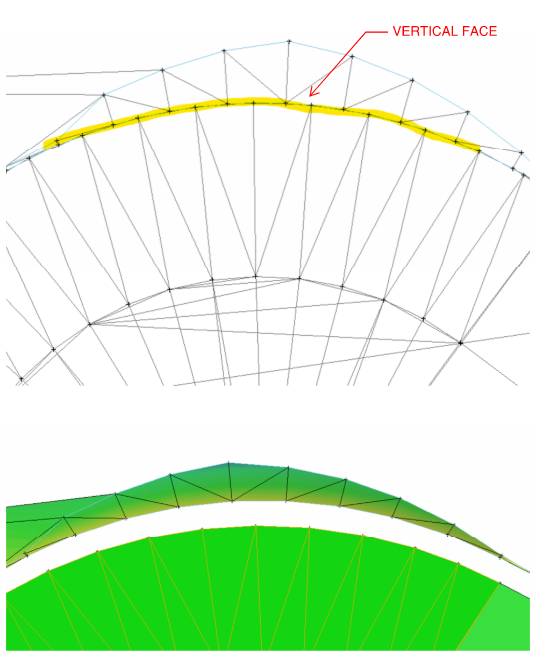
I get a lot of FDOT surface files for lettings where the multiple surfaces are built off of CAD points. The vertical faces don’t tie and I assume it’s b/c the horizontal distance between the CAD points are on top of each other - the horizontal distance between them is 0.00’. What method or process is used to make the tie?
Suface File: AMG-3SURFACEPR_EW01.xml
TBC operates in a similar way. The design software has something written internally that allows (when building in a corridor) to construct vertical faces, but building a tin in general doesn’t allow more than one elevation point at the same coord. I expect they do something like bumping the line a very small invisible amount .001 or something to that nature. If you redefine in a corridor in TBC, it will allow you to reconstruct the vertical faces. But if you explode and try to rebuild a surface from the resulting triangles, it will flag errors in the same way. I expect Alan knows technically how this works inside of the software.
To re-establish the vertical line, I expect you would have to reconstruct in a TBC corridor.
Otherwise, if you have the horizontal linework, a workaround would be to build a surface of the upper (or lower) section, offset the horizontal line that defines the vert break .01’ and drape over the surface. Basically, you would need to utilize the triangles for one plane of the surface and then make break lines for the other and tie them back together in a surface (with a minor gap introduced). Or if you are provided the 3D line strings/feature lines, bump line strings a tiny amount and reconstruct the surface.
This is why the Nudge Line command was made.
1 Like
I drew a linestring along the CAD points, added as a member on the surface, and then nudged the line. That resolved the issue. I’ll study up on the nudge command a little more so I can use it to nudge the points.
2 Likes
There is no nudge points function currently - you can nudge a line sideways or the nodes of a line longitudinally to remove vertical faces in Profiles and sections.
To nudge points you still would need a line to determine the direction to nudge the points in and each point has to be computed individually.
Do they give you the lines as well as the points, if yes, you can exclude / remove the points from the surface and nudge the line. If the line is created dependent on the points then that is trickier because you have to nudge the points to move the line.
We could make our tool do that if the line is dependent on the points because I don’t think that it does that today. If there are non dependent lines and points and both are in the surface then you need to nudge the line and then remove those points from the surface because they will still be in the original location.
I would have to test the file to see what you are getting - I don’t believe that the TBC surface is created using lines dependent on the points but I may be wrong there.
Alan
Hey,
Can you email me your surface so I can take a closer look at how the data is structured?
Thanks,