One of our Dozer operators called me out to a job because he had some weird dips in his grading. I checked my V.P.Is along the line on my DXF and noticed they were horizontal instead of vertical. Thinking I made a mistake I went back and checked my VCE I exported it from and they are all vertical V.P.Is. Any ideas why it changed them? I’m a newer user, I don’t know if its something I’m doing wrong before export or a export issue? Does it make a difference if its vertical or horizontal as long as the elevation is correct?
Joe
The ability to have VPIs on the 3D lines is a TBC only capability. The DXF file / AutoCAD file format lines support 3D lines but the lines have to have all nodes as 3D nodes i.e. the XY and Z are all at the same place. In addition AutoCAD DXF / DWG doesn’t support 3D arcs other than by drawing a 2D arc on a tilted plane (which is not the same thing at all). so if we have an Arc in a line in TBC that is elevated at points at the ends and or in the middle of the arc, the arcs have to be chorded into 3D chorded lines to represent the arc for use in a DXF or DWG file. When you select lines for export in TBC, if they are 3D TBC will do the chording approximation and create a 3D node (XYZ) at all the VPI points because that is all that a DXF / DWG file can use.
For linework for the field, many people output 2D lines for guidance and maps, alignments for Road Centerlines and surfaces for the 3D information because of this shortfall. While the Siteworks and Earthworks systems say that they support the TBC VCL formats they really don’t support them the way the format was intended which would solve all of the above issues - they convert the data into a surface and linework file (DXF and TTM in Siteworks, DSZ in Earthworks) that have the above traits.
We recommend that while the VCL full support is desirable, outputting a curvilinear set of 2D lines for guidance and a surface model for 3D is the way to go right now.
I don’t think this however will make the difference in the surface model that you are seeing, the blade runs off the surface model and only uses the lines for guidance - so if there is a dip, the dip must be in the surface model - that could be down to the way the triangles have formed in that area and you may need to add a breakline into the surface to force the triangles / surface to do what you need it to do.
Remember also that the elevations of a line are computed along the line, if the dips are in a curved section it could be that the curve is intended to lie on a plane made of 3 points but because elevations are computed along the line that is creating a sag or high point in the line.
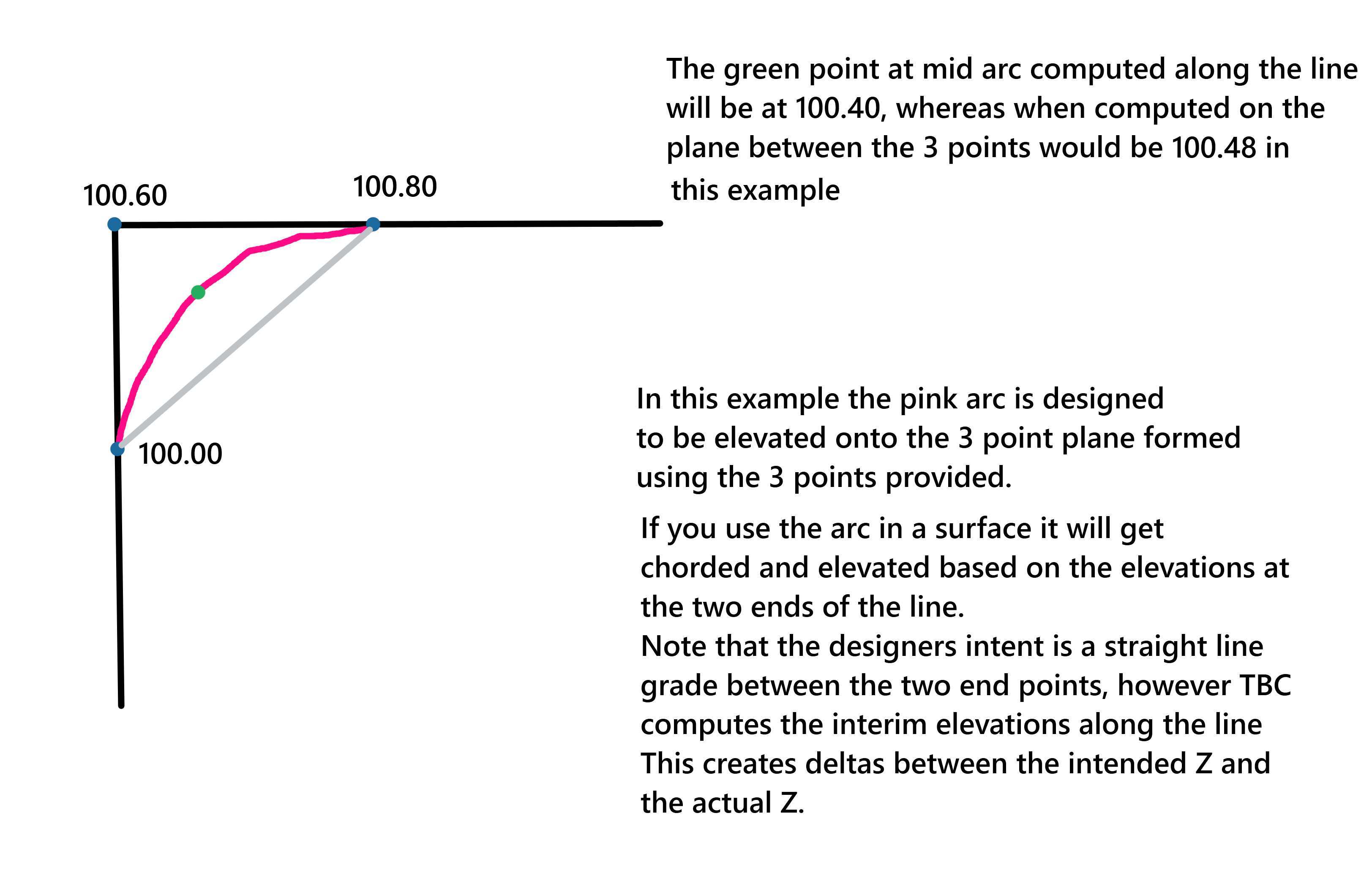
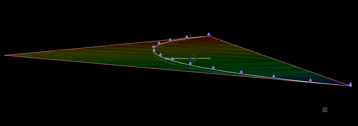
You can see the difference in the vertically exaggerated image below
The degree of difference all depends on the elevations and the directions of slopes at the return / parking island as to what you will get along the line - this comes back to the discussion we had the other day about the “Grading Framework” for parking lots and road intersections etc.
Hope that this helps
Alan