November 15 2021
Today Trimble announced the release of Trimble Business Center v5.60. The new release continues to focus on customer requested usability improvements and the most commonly requested features and enhancements for Construction and Survey / Geospatial Applications.
As always Rockpile Solutions is actively engaged in the Beta Program and have provided some significant feedback for this release, especially around the use of the new Reference Files / Reference Surface functionality and the enhanced bi-directional DWG support of Blocks and Multiline Text objects. From our testing we are extremely happy with this release and feel that it offers significant advantages to our users.
In addition we have published a new installation package for the RPS All Tools command library that adds some new commands, some significant command improvements that leverage the new capabilities of v5.6 as well as some minor defect fixes.
Warranty Date
Warranty Date for TBC v5.60 is November 1 2021 - if your warranty expired prior to this date, contact your dealer for a new warranty contract.
So What Is New In TBC v5.60 - Here are the Highlights for Contractors
The following enhancements have been made in Trimble Business Center version 5.60
Reference Files and Reference Surfaces
The largest improvement in this release for contractors are the addition of the new Reference Files and Reference Surfaces commands. This was the second most requested feature after the Rotate Plan View functionality that was added in the TBC v5.52 update.
Reference Files allows you to add any number of TBC projects as reference files to the current project. Reference files can be turned on and off using a view filter switch in the same way that layers can be turned on and off. A Reference file can be set to a single color so that it is clearly delineated from the current project data. A Reference File can also have its own view filters and those can be used to limit what data is visible in the reference file over and above the current projects view filter settings. Objects in a reference file can be snapped to for the extraction of locations or elevations or distance along etc. PDF Sheets that have been referenced into a reference file can also be displayed in the current project allowing fast reuse of the PDF sheets between projects.
Surfaces in a reference file can also be added to the current project using the new Reference Surface control. A Reference Surface is just a reference back to the surface in an attached reference file, however a reference surface can be used for volumes, as a reference in a corridor, sideslope, utility trench or tie slope object. All of the RPS Commands that reference surfaces have been updated to support reference files fully. You cannot Add / Remove members to / from a reference surface.
Reference Files and Reference Surfaces provide the compelling benefits to work groups using TBC on a common project
- You can subdivide the work required on a project and store your project files in a common folder on a network drive. Files being developed by one person can be used by another person in the project that they are working on. As changes are made and saved in a reference file, the user of the referencing project gets notified through the project explorer that an updated reference file is available, and they can refresh the reference file to access the latest version of the information. For example one person could be working on Finished Grade and Existing Grade surfaces, while a second person can be developing a utility model. Both people can reference each others project - the utility person can build trenches to reference surfaces that reference the surfaces of the other person. The earthworks modeler can also reference the utility model to see its progress including all of the trenches etc. that have been created.
-
Re-use of PDF pages - people have often commented to me that when revisions of sheets come in or when a new version of a set of CAD data is provided, that they develop a new project for the revision information. Recreating all of the PDF sheets for a linear project can take time to import and georeference all of the data from an older revision project. Now you can simply reference the older project into the current revision project and reuse the data that you previously prepared.
-
Revision comparisons - when you get a Rev 1 and Rev 2 CAD file for a project, simply open each set of CAD files in a separate TBC project. Create a New project and add the Rev 1 and Rev 2 projects as reference files. Set Rev 1 to one color and set Rev 2 to a different color and lineweight and you can readily see the differences between the revisions. Use View Filters in the two reference files to create common groups of data e.g. for Parking Areas, Buildings, Landscaping etc. so that you can readily compare like data between the revisions.
If you want to copy data from a Reference File into a different project - use the new RPS Copy to Clipboard command that uses a virtual VCL file to copy and paste information from any TBC view into a different project. All object copies take all dependent objects i.e. a surface TIN made from points and lines will copy the point and line data between the projects. RPS Paste command has been updated to recognize the virtual VCL format data on the clipboard and write it into the current project file. The copy paste function also works with Plan Sets, Sheet Sets and Sheet level data.
Text and Block Compatibility With AutoCAD through DWG Format
In prior releases of TBC up to 5.52, when you imported Text from DWG or exported MultiLine Text from TBC to DWG you had the following problems
- Blocks imported into the Sheet View were scaled 12x too big (Block importer did not recognize the Sheet Units of Inches for Paper Space information from AutoCAD’
- Multiline and CAD Text objects imported from AutoCAD never looked the same, they were not wrapped in the same places, character spacing was off and embedded smart codes in the text blocks while supported were not being read correctly.
- Multiline Text data exported from a TBC project were not written with a text block width property so the text in AutoCAD came in ass a single unwrapped line of text.
- Imported Blocks from AutoCAD did not support the view filter overrides correctly, and would not plot in the override colors defined.
The overall result of sharing text between TBC and AutoCAD was poor and resulted in a lot of rework of the information provided, especially important for the Field To Finish workflows of surveyors doing traditional land survey or cadastral survey work.
All of the above issues have been addressed and the net result is no rework and a high degree of compatibility between AutoCAD and TBC for Text and Block items.
Refer to our other posts today on AutoCAD smart format codes embedded in Multiline Text Objects
User Profile Manager Command - For On Line User Profile Management
Over the past few years there have been many requests to provide faster and easier ways to manage your own personal system after a TBC update. In this release Trimble has added an online service, linked to your Trimble ID that allows you to store the following information with your Trimble ID account.
- Project Templates - you can now save selected project templates to your user profile in your online account so that you can always have them available between versions and between computers that you may use (e.g. Home and Office computers). When you start a new project you can select a local Project Template or a template from your User Profile Templates. This functionality is found in the Create New Project process or in the new command called User Profile Manager.
- User Options - you can now save and restore your User Options to / from your user profile in your online account. These are the settings created and managed by the Support - Options command.
- Menu Ribbons, Toolbars and Command Shortcuts - you can now save and restore your Menus, Custom Toolbars, Quick Access Toolbars and Command Shortcuts to / from your user profile in your online account. These are the menu and toolbar configurations created using the Support - Customize Ribbons, Support - Set Ribbon Tabs, Customize Tools and Support - Define Command Shortcuts commands.
The User Profile Manager Command provides the ability to Backup the above options, Restore the above Options and Clear the defined options from your Online profile.
In order to use the above functionality you need to have a Trimble ID setup and be signed in to the Trimble ID server. If you do not have a Trimble ID, go to Support - Options - External Services - Profiles and Create a Trimble Identity Profile and name it Trimble ID. Once created click Sign In and that will open the Trimble ID website. If you have a Trimble ID simply enter your Username and password. If you do not have a Trimble ID create one by clicking the Create an account link and follow the instructions.
Pavement Line Marking Feature Extraction
For those of you that use the Feature Extraction workflows in TBC for Point Clouds, a new Line Marking feature extraction tool has been added that allows solid lines, double solid lines and dashed line markings to be tracked and extracted in an automated manner. This process will work with any point cloud data format.
The following video showcases and highlights some of the other improvements in TBC v5.60
SHIFT + Right Click Context Menu for CAD Tools
In addition to the standard Right Click context menu options that relate to the object type(s) selected, TBC now has a SHIFT + Right Click menu that shows CAD tools like
Delete
Copy
Move
Rotate
Scale
Change Elevation
Explore Object
Match Properties
Properties
Imported Files List - Sort Order
Correcting a change made in TBC v5.52, you can now select how you manage the Imported Files list in terms of its sort order. You can now sort by Filename or sort by imported order. Simply right click on the Imported Files section of the Project Explorer to access the new options.
MSI Manager Improvements
You can now more easily move materials and site improvements between categories in the MSI Manager. You can also group select and copy Materials and Site Improvements To / From an External MSI Library file. All Move and Copy functions are on a Right Click menu as well as icons in the command header area.
Create Profile Proxy Command
The CreateProfileProxy command was always a hidden command in TBC until now. This command allows you to add linework that crosses or runs approximately parallel to a selected alignment to the profile view of an alignment. The command converts the selected lines into the station and elevation coordinate system of the selected alignment for display and drafting purposes. This allows you to plot e.g. Pipe Inverts or Crown of Pipe or Culvert Lines or Ditch Profile Grade Lines or Wall Top / Bottom Lines in the Profile view of a selected alignment.
Vertical Design Improvements
A new switch has been provided in the Vertical Design controls “Automatic Z Values” which provides automated elevation of connecting lines when instructions are applied to one of the lines. For example take 2 lines that meet at a T intersection. If we add an elevation 100.00 to the main line through the T then the side line at the T is elevated to elevation 100.00 also. If we then add a grade rule of 5% to the main line through the T creating an elevation at the T point of 103.12 then the sideline now has an elevation of 103.12 etc. Entire networks of lines eg Subdivision centerlines are gradually elevated as we add more rules to the vertical design. To some degree this replaces the need for connector instructions.

Layer Manager Improvements
The standard TBC Layer Manager now has a Filter control allowing you to enter a regular expression to filter the complete layer list e.g. if you have a group of layers called CADXS - ??? then you can enter CADXS or XS into the filter control to reduce the layer list to just those layers with those characters in the layer name. This reinforces the workflow methodology that we use to prefix all of your layer names with e.g. EX - or FG - or CADXS - or UTIL - or SHEET - etc. as this will now allow you to get at those specific layers quickly and easily.
You can also now resize the column widths of the fields in Layer Manager to make them more readable when you resize the entire Layer Manager window.
Measure Distance Command Improvements
The slope value between the selected points is now included in a stored measurement
Measurement Results

Stored Measurement Properties
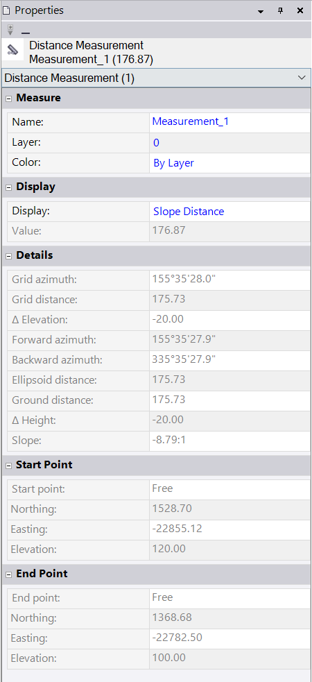
In the properties pane for a stored measurement you can now select the value to display on screen along with the stored measurement. The options here are
Slope Distance
Horizontal Distance
Vertical Distance
Azimuth
Slope

These are great model QA or Data Querying Tools for Data Prep now - you can use this to determine or check cross slopes between strings and also to extract slopes from converted cross section data. Being able to label these on a drawing is helpful when building corridor or sideslope or slope designer models using tables or data entry methods for variable slope surfaces.
Coordinate System Enhancements
As usual with each TBC release there are a number of coordinate system enhancements for specific regions of the world, however in this release the display of Point Properties has also been enhanced to now display
- The Zone Name and Geoid Model name for a Grid Coordinate Point
- The local datum name for a Local Coordinate Point
- The global reference datum and global reference epoch for a Global Coordinate Point
TBC Reports have also been updated to include the selected global datum.
Works Manager Improvements
You can now import point data from SCS900 / Siteworks work order spj files directly from Works Manager using the Import Work Orders from Works Manager command.
Smart Text Improvements
The following enhancements have been made to the Smart Text capabilities of TBC
Comma Separators in Smart Text Objects
Support for comma separators in text values displaying numbers in the thousands (1,000) or millions (1,000,000) can now be added into Smart Text by adding a minus sign in front of the number of decimal places required in the text.
Additional Utility Smart Text Object Codes
The following Smart Text Codes have been added for Utility Objects
UH = Utility Height of Utility Nodes that have a Rim and Invert elevation value
BE = Utility Elevation - Beginning of Pipe / Cable (Typically Invert)
EE = Utility Elevation - End of Pipe / Cable (Typically Invert)
In addition the Utility Node objects now also support the alternative units and math functions in the Smart text.
Labeling Improvements
The Label Style and Label Table Style Managers have been enhanced to provide more customizable control for adding attribute information into labels and tables created in projects for points, lines and polygon objects. The customization allows you to add label prefixes for selected attributes or column headers for tables. Labels of attributes can be stacked horizontally or vertically. When stacked vertically you can now control how many attributes are listed on each line of data in the label. For labeling attributes, you can select which attributes will / will not be included in the attribute labels from the attributes that are available for each point type.
The label properties pane has been enhanced in line with the above changes. Changes applied to the properties pane are automatically reflected in the graphical representation of the objects selected.

*Label Tables for Manhole and Other Point Data / Takeoff Count Object Schedules

These improvements can be used in conjunction with Takeoff processes for entering Area, Length and Count Object types in order to produce labeled drawings and schedule tables for use in bid submission documents or for field crew drawings and diagrams to assist layout and machine control operations.
Utility Object Display
In prior releases of TBC, small utility objects (small pipes, conduit or boxes defined using custom utility shapes would not display / could not be created. Objects smaller than ~6cm in diameter could not be created with a wall thickness and if created as a single shape (like a circle) they would be displayed as a pentagonal solid. The display of these objects has been improved for objects as small as 1cm in diameter, ideal for small conduit and conduit groups, resulting in improved display and visual clash analysis
A defect that was found in custom utility shapes has / has not been fixed in this process (6 conduits were shifting at a node in a utility line).
Other Areas of Improvement
Significant additional functionality and improvements have been added to the Tunneling, Monitoring, Mobile Mapping, Point Clouds, Photogrammetry and Survey Work Processes that are not covered in this post - please refer to the Release Notes for more details.
Bug and Defect Resolution
The following major issues have been fixed in this version of TBC:
- Processing time for extracting scan points from a point cloud and assigning them as
as-built tunnel points increased substantially in TBC v5.5x when compared to earlier
versions of TBC. - The Edit Corridor Template and Insert Corridor Template buttons at top of the Edit
Corridor Template command pane did not work if you had a non-corridor object
selected. - Excavation and embankment volumes were different by 1.5% (using the same
sampling distance and settings) when you calculated volumes for corridor projects
using the Corridor Earthworks Report and the Material Volumes Report (in REB
Tools). - Elevation labels did not appear on a cut/fill map as specified. The number of labels
(based on gridlines) exceeded the limit, so the limit has been raised. - Cross Slope and Cross DZ rules did not work in the same vertical design if the design
included multiple CAD lines at the target location; only one of the lines was used in
the calculation. - Multi-selecting files in the Import command and then choosing Select in the context
menu deselected everything. - The Takeoff Report was missing strata volumes if one strata had a thickness of 0.0.
- In the Surface Info Report, you could not set an elevation range if no surface was
selected. - You encountered an error running the Area/Length/Count Report when you had
Display Data in Report View selected and Show All Details enabled. - You encountered an “unexpected network failure” error when publishing a
boundary created from a linestring to Works Manager. - When splitting plan and profile data into multiple views in a sheet set, the Profile
View data did not match the Plan View data. - You encountered an export error when publishing data to Works Manager; this was
due to the combination of enabling the Cleanup VCL property (to cull dependent
objects from the VCL file) and including a vertical design.