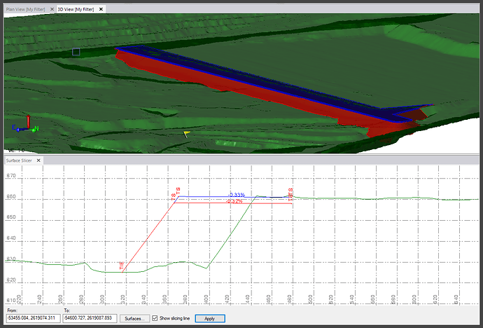
In the example data provided, the backfill designs were provided as two DXF files containing 3D face information that represented the top of the backfill design and the top of the capping layer only. There was no front face model at the slope angle desired for the backfill operations. Without the front face slope information, the volume calculations will be wrong for the resulting work orders, in addition the full width of the design model will not be available to the GCS900 machines when you provide them with the surface models for operations.
In the absence of the front slope information from the designers, you can add that information by using TBC commands like Create Surface Tie or Create Sideslope command or by using RPS commands like Slope Designer.
The video below shows how to build the sideslope model elements for the backfill and capping surface designs. The process steps include
- Using the provided 3D face data to create the breaklines around the top of slope using the RPS Takeoff Lines command. You can use create Linestring command as an alternative command.
- Using the Slope Designer command to create the sideslope that ties with the existing surface. You can use the Create Surface Tie or Create Sideslope commands as an alternative command.
- Create the surfaces for Backfill Design and Capping Design from the computed 3D linework
- Adjusting surface computation settings and surface properties to get the desired end results
- Tidying up the surfaces with the Trim Surface Edge commands
- Creating a boundary object for the Work Order generation process.
