I had a user ask me these questions relating to a project they were working on
Within the interior paved areas there’s a flow line and spot elevations. How do I create spot elevations in some places and/or a flow line with elevations perpendicular to where a grade break crosses the flow line?
How do I deal with the Grade Break if there’s no elevations at the curb line?
How do you change the text for the Proposed Buildings? The wording and/or the FF Elevations?
I’ve cleaned up and prepared the Original Surface but have not created it. What is the correct process for creating the OG/Existing Surface form a PDF. I might have CRS for this process and need a punch in the arm?
The video below tries to answer the questions but they raise some important questions that you have to take into consideration as follows
- When an engineer gives you flow line elevations for e.g. start and end points and then also catch basins in the flow lines and then in addition they draw slope arrows in this case from the building to the flow line e.g. that show a slope of 3.9% down to the flow line from the building - should you use it? The building is elevated and the flow line is elevated using the spot grades that they are giving you, so do you also use the cross slopes as well at those specific points - bear in mind that you have to fix something - the building only has one elevation so we can assume that is fixed, the flow line is at a constant offset to the building, and has been elevated using spot grades - so do the slope arrows indicate something additional that you have to take into account - in many cases the slope indicators are drawn as a “for information item” but at the specific location that they are drawn they may or may not match the slope between the building and the flow line. If they match then they are of no additional value, if they dont match the question is should they match or do you need to change / add an extra elevation into the flow line to make it match and if you do that what does it do to the flow line because it will likely change the vertical profile of the flow line and is that what was intended

In the image above you can see that the highlighted flow line has an end elevation of 16.73 and there is a catch basin B2 with elevation 16.22, and they tell you that the slope along that line segment is 0.7% - the distance between those two points is actually 74’ and the DZ is 0.51’ so you have a slope of 0.689% which is being rounded to 0.7% - so the elevations are giving you more accurate info than a rounded slope %. So the same likely applies to the cross slope which indicates at that specific point it is 3.9% - yet if I measure the slope between the Building line that has elevation of 1016.9 and the flow line that using the Catch Basin and other line elevations gives me an elevation of 1016.26 and the distance between the building and the flow line is 17.5’ so the slope is 3.65% not 3.9%. If you use 3.9% then the elevation at the flow line would be 1016.217 which is the same elevation as the Catch basin so that will introduce a flat spot in your flow line (Water Pooling) and also will increase the slope of your flow line slightly (which might get it to 0.7%) but what did the engineer intend? That is the million $ question …
This is the flow line Profile using the elevations only

If we use the cross slope data as well then the flow lines look like this
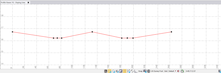
By adding in the "flat Spots, the drainage slope line increased to 0.76% at one end and 0.81% at the other (should have been 0.7% and 0.7% according to the plans.
If all the data is needed then the flow line slope is wrong in the plans. If you ignore the cross slopes then the flow line slopes are closer to the plans but the cross slopes where they are provided are not exactly correct - they are also rounded so that makes it hard to determine what is right and what is wrong - welcome to the world of Data Prep / Modeling.
Anyhow, I will get off my High Horse here and the video shows how to solve the questions - just be aware that I am answering the questions not solving the problem.
If any modeler out there wants to add to this discussion - please feel free to do so.
My general rule is to use the elevations and check the cross slopes and long slopes - but expect the slope values to be both rounded and off - and then decide what the engineer wants you to do or give them a call to clarify the intent.
Hope that this helps - since it is a Takeoff Question, we are in the weeds here and likely the discussion would cost a couple of $c more or less than what we would bid either way - so likely not really an issue - but if this was a model for Machine Control and a finished product - i would be asking do they want a catch basin in the middle of a flat spot of do they intend the slopes to end at the rim of the Catch Basin. Only you know what engineers want where you live and work so you can decide the outcome based on your experience.
Alan