Smart Label Command

Command Release History
- Version 1.0 of the command was released in v2026.2 of the RPS Command Library in May 2026
Command Licensing and Default Menu Location
- The Smart Label Command is part of the RPS Smart Suite and RPS Smart Data Prep Command Library
- The Smart Label Command is located on the RPS Smart Suite menu ribbon
- The Smart Label Command is located in the Drafting menu group
Command Description
The Smart Label command provides a fast and easy way to label objects or create text annotations on drawings using Smart or Normal Text items, with or without leader lines. It also provides an easy way to add a leader line to Text items that aleady exist in the project database. The Text Labels can be stored in an RPS Settings library so that they can be easily selected and reused on any TBC project.
Video Demonstration and Training Project Data
The following video shows the RPS Smart label Command in use, and explains all of the settings and options available.
The zip file below is the Smart Label Test Track project used in the training video, if you want to try out the labeling options, this is a good place to start.
Smart Label Test track.zip (2.0 MB)
The Excel Spreadsheet below is the set of labels that are predefined within the Smart label command itself. You can use this spreadsheet as the basis for creating your own Smart labels for use within the command. Use RPS Settings, Smart Label Settings, upload from Excel option to load the Excel File contents into your Label Library.
Smart Labels - Master.xlsx (43.7 KB)
Command Modes Overview
The Smart Label command provides 3 main workflows for labeling and annotating drawings
Existing Text Workflow
This mode provides two options to add leader lines to existing text labels.
Move Text Mode
Allows you to add a leader line that starts at the current text location and moves the text to a new location connected by the leader line.
Target Point Mode
Allows you to add a leader line that starts at the arrow / leader point location and ends at the selected text label insertion point.
New Text Workflow
The new Text workflow provides two options for creating all new text labels in your drawings.
Simple Text Mode
Provides the ability to create user defined text labels without Smart Text Code inclusion, with or without leader lines. In this mode, the labels are defined “on the fly” by the user.
Smart Text Mode
Provides the ability to create labels from predefined label styles stored in your RPS Settings library that utilize all of the TBC Smart Text codes, with or without leader lines.
Existing Text Label Workflow
The Existing Text Label command dialog looks as follows for the Move Text option
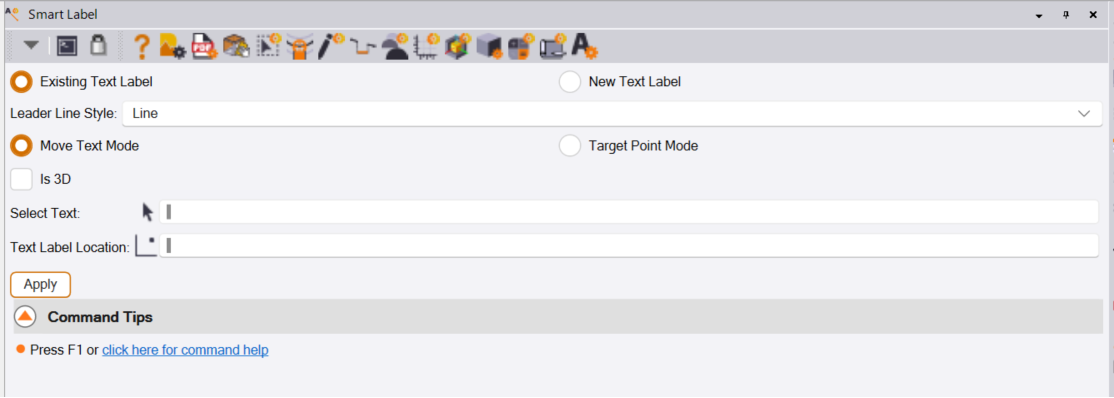
Existing Text Label Radio Button
Select the Existing Text Label radio button to use this mode
Leader Line Style
Select the Leader Line Style, there are 4 options
- Line - this is an angular leader line
- Spline - this is a spline curve leader line
- Line with Arrow - this adds an arrow head to the line leader line
- Spline with Arrow - this adds an arrow head to the spline leader line
Move Text Mode Radio Button
In this mode, you select the text that you want to add the leader line to, and then move the text to where you want it to be. The leader is created with it’s arrow / leader point located where the text was, and the tail of the leader where you move the text to.
Select this option if you are using the Move Text Mode
Target Point Mode Radio Button
In this mode, you select where you want the arrow / leader point to start and then select the text to which you want to connect the leader. This leaves the text in its current location and adds a leader line to the text pointing at where you want the text to reference.
Select this option if you are using the Target Point Mode
Is 3D Checkbox (applies to both modes of operation).
If the Is 3D Checkbox is enabled, the following scenarios are possible
- Leader point selected is 2D - the elevation of the text will control the elevation of the leader point
- Leader point is 3D but text elevation is 2D - the leader point will be used to elevate the text
- Leader point is 3D but different to the text elevation - the leader line will slope between the two elevations.
Where possible the text and leader will be 3D, if both the leader location and the text elevation are 2D then the text and leader will be 2D.
If the Is 3D Checkbox is disabled, the following scenarios are possible
- Leader point selected is 3D - the leader will use the XY location only and be set to 2D
- Leader point selected is 2D - the leader point will be 2D
- The Text location is 3D - the text elevation will be reset to 2D
- The Text location is 2D - the text will remain 2D
The leader and text will be 2D in all scenarios.
Where possible the Text and Leader will be defined either in the same elevation plane (2D or 3D) or where the text ad leader points have different locations, a sloping leader will be created. We are trying to avoid the scenario where the Text or Leader Point is 2D and the Text or Leader Point is 3D. The only potential issue here is that the text is meant to be at a specific elevation and we change it to a 2D elevation because of these rules, and because the Is 3D checkbox was disabled.
Move Text Mode Function
Select Text
Select the text that you want to add a leader line to. The text current insertion point location becomes the leader arrow / point location.
Text Label Location
Select the location where you want the text to be in relation to its original location (this also becomes the leader line tail location).
As soon as the Text Label Location is selected, the text will move and the leader line will be created.
Target Point Mode Function
The Existing Text Label command dialog looks as follows for the Target Point Mode option
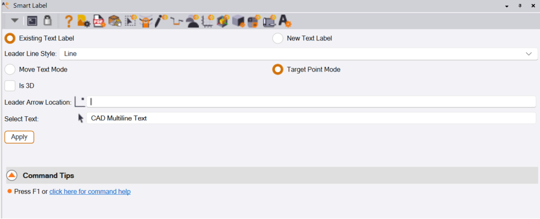
Leader Arrow Location
Select the location at which you want the leader line to point / arrow.
Select Text
Select the text label to which you want to connect the leader line.
As soon as the text label is selected, the leader line will be created between the selected location and the text label.
New Text Label Workflows
The New Text Label - Simple Text Mode / Smart Text Mode Workflow command dialog looks as follows
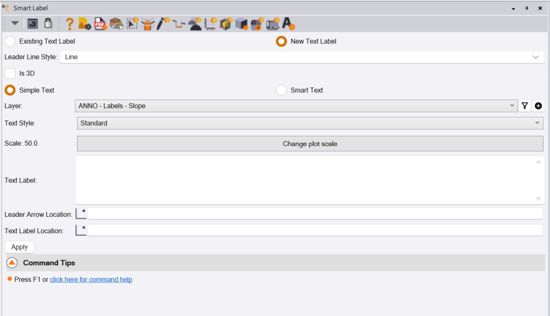
In this mode, the user controls the type of leader line, the layer, and the text style to use. The label is then defined and placed, using a leader line location and a text location, or just a text location if the No Line leader line style is selected.
Leader Line Style
Select the leader line style that you wish to use from the following options
- Line
- Line with Arrow
- Spline
- Spline with Arrow
- No Line
Note that in the Existing Text label workflows, there wasn’t a No Line option in the Leader Line Styles, this is added for this mode of working. The Leader Line Styles are otherwise the same.
Is 3D Checkbox
In this mode, because you are creating both the text and the leader lines, the rules for 2D / 3D creation are slightly different to those of the Existing Text Label workflows. In this mode you are selecting a leader location and a text label location. Either location could be 2D or 3D, however our goal with the label is to place the label in 2D or 3D and have the Label and the leader lie on the same elevation plane.
In the Smart Text mode, many of the labels require the selection of reference objects i.e. Points, Lines, Alignments, Surfaces etc., all of which can be 2D or 3D in nature. The text location that is selected will typically be a free point location (2D) however there is nothing stopping you from snapping to an object that has 2D or 3D location.
Rules
- If the label is using a reference object, the reference object, if 3D, controls the elevation of the leader and text location
- If the label is using a reference object, and the reference object is 2D but the text insertion point selected is 3D then both the text and leader location will be 2D.
Simple Text or Smart Text
Choose between the two options as follows
Simple Text - this is a text label or a block of text that will be placed with or without a leader line. The text in this case is typed in each time you want a different label. The text in this case should be simple text and not include any TBC Smart Text codes.
Smart Text - this is a predefined text label stored in your RPS Settings library. To create Smart Text labels, use RPS Settings to create the label (see below). These labels can include text and embedded Smart Text codes that reference the properties of the reference objects selected e.g. Station and Offset in relation to a reference line, Point Number, Feature Code, Northing, Easting, Elevation or Latitude, Longitude, Height of a point, Surface Elevation or Slope of a Surface, Geometry, Length, Area or Slope of a line etc. The Smart Text labels also contain all of the text properties required like Whiteout, Text at Centroid (areas), Text Along (for Line Labels), the type of Leader Line and how it will be created (Fixed or Variable Geometry), AutoFlip, Text Height, Text Font etc.
Simple Text Workflow
The Simple Text workflow dialog looks as follows
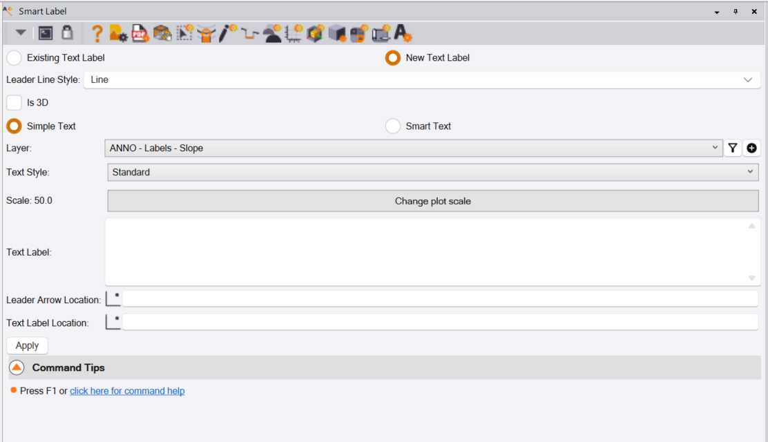
Layer
Select the Layer for the text label being created
Text Style
Select the Text Style to use for the label. Text Styles are defined and managed by the Text Style Manager. You can access that from the header bar of the Smart label command, or from the RPS Support menu ribbon - System Management command group.
Scale: e.g. 50.0 - Change Plot Scale button
Most of the Text Styles defined by RPS are stored in the project template that we provide to our users as a starter template. The Text Styles are mostly defined in Sheet Units. This means that the height of the text in the plan view is dependent on two elements, the Text Height of the Text Style e.g. 0.06in (sheet units) and the Plan View Plot Scale e.g. 1” = 50’. In this scenario, the height of the text in the plan view will be 3.0’ (0.06 x 50), and when a plot sheet is created using e.g. Smart plot at 50 scale, the text height on the sheet will be 0.06 inches. Note that TBC computes the height of the text in the Plan View at the time the label is created. TBC does not later update the text height if you later change the Plot Scale. For this reason we make the Plan View Plot Scale visible to you here in the dialog, and allow you to change the Plot Scale before you start deploying labels.
Text Label
Enter the text for the text label that you wish to create. You can copy and paste data from other applications into the white box that defines the text for the label if needed. Use CTRL C and CTRL V to copy and paste, or you can Right Click in the white box and select Paste. In this mode you should not use Smart Text Codes in the text label. To use Smart Text codes, use the Smart Text workflow (see below).
Leader Arrow and Text Location
Depending on the type of leader line that you selected i.e. No Line vs Line or Spline leader options, you will be asked to select a Leader Arrow location (when Leader Line styles were selected), and or a Text Label Location (when any type of Leader or No Line is selected). When leader lines are used, the leader line will stretch between the leader arrow point and the text label location point.
Leader Arrow Location
Select the leader arrow / tip of leader line location. Note you can use snaps here to snap to point, line, surface, free location etc as you see fit.
Text Label Location
Select the text label location (text insertion point). Note you can use snaps here to snap to point, line, surface, free location etc. as you see fit.
The text label will be created as soon as the Text Label location is selected.
When this field of the dialog is active, you can use the Left, Right arrows to change the orientation nof the text labels, the Up and Down arrows to change the height of the text of the text labels. You can also use the CTRL + Hover over a line to orientate the label parallel to the line (hover over the left or right side of the line and press CTRL on the keyboard to flip the text (when AutoFlip is disabled) to rotate the text by 180 degrees). You can also use SHIFT + Hover over a line to orientate the label perpendicular to the line.
Smart Text Workflow
The New Text Label - Smart Text Mode Workflow command dialog looks as follows
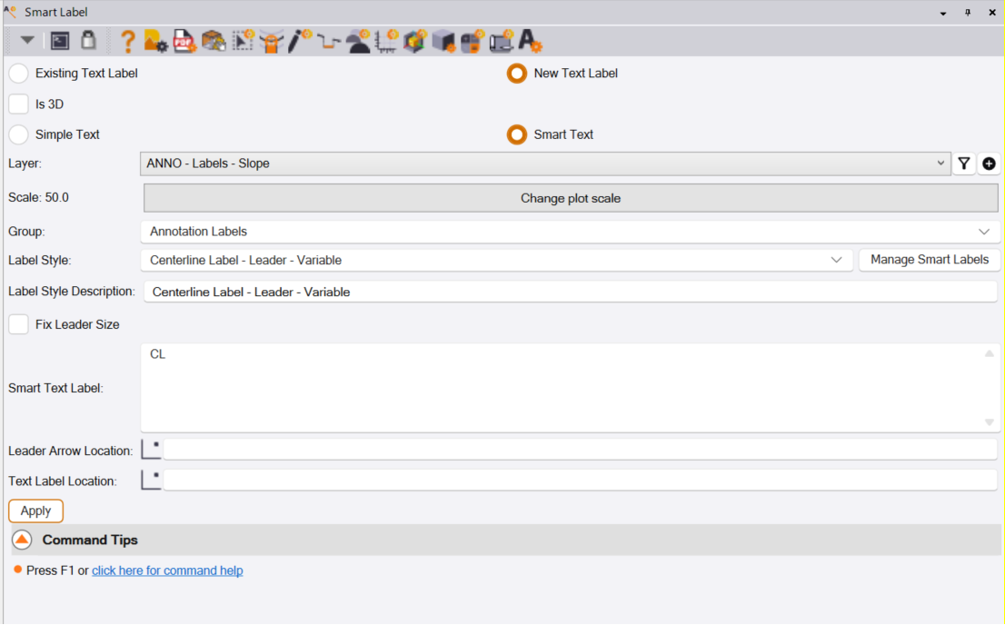
In this workflow, the settings that are common to the Simple Text mode have the same function as the Simple Text workflow. The main differences between the two workflows are as follows
- The Smart Text workflow uses labels that are predefined using RPS Settings - Smart Label Settings. This allows you to create Smart Label Groups and Smart Labels within those groups. The groups are defined to organize the Smart labels, so that it is easy to find the label that you are looking for, and quickly recognize its use case. The command includes more than 100 predefined labels that you can use directly. You can use these labels as the basis for new labels that you require as needed, or define the labels directly in the RPS Settings dialog (see below).
- The Smart Text workflow uses TBC Smart Text codes in the text labels that are defined. Smart Text codes utilize properties of selected reference objects (points, lines, surfaces, alignments etc.), and dynamically updates the values displayed in the text label if the source reference object changes (is moved, elevation changes, code or point number changes etc.)
Group
Select the Group that you want to select your Smart Text Label from. The standard library contains the following groups, the table describes the types of label to be found in the group.
| Group Name | Description |
|---|---|
| Annotation Labels | General labels like Start / End of Project, Start / End of Construction, ROW, New ROW, Easement, Proposed Easement etc. |
| Area and Perimeter Labels | Areas of polygons, perimeter of polygons, use with Smart Feature Area, Length Width features, apply depth and conversion factors to compute volumes and tonnage |
| Curb Elevation Labels | Elevations of curb and gutter lines, flow lines, top back of curb lines etc. |
| Line Geometry Labels | Full line geometry values like Name, Length 2D and Length 3D |
| Line Segment Labels | Line Segment Geometry like Radius, Length 2D, Length 3D, Instantaneous Slope, Bearing etc. |
| Location Labels | Labels like Station and Offset or Northing and Easting of a location in relation to a line or alignment |
| Point Labels | Labels for Points including Point Number, Feature Code, Northing, Easting, Elevation, Latitude, Longitude, Height, Station, Offset, Elevation etc. |
| Profile Labels | Labels for profile view including Station, Elevation, VPI Station, VPI Elevation, High Water Level, High point, Low Point etc. |
| Sheet Content Labels | Labels for Dynaview Scale and Vertical Exaggeration |
| Sheet Title Box Labels | Labels for Title Box and General Sheet Annotation including Company Name, Address, Phone, Fax, Email, Web, Coordinate System, Project Details, Sheet Number, Sheet Count etc. |
| Surface Labels | Labels relating to surfaces e.g. Elevation, Surface Slope, Surface Slope in Specified Direction etc. as well as Point To Surface or Line To Surface Elevation Deltas for Cut / Fill, Clearance or Depth of Cover Labeling |
| Utility Labels | Labels for Utility Pipes, Cables, Conduits, Structures and Fittings |
| Volume Labels | Labels for Cut Fill Maps e.g. for Pond Earthwork Volumes, Pad Volumes, Stockpile Volumes that dynamically update with Design Changes of position or elevation |
Label Style
Pick any one of a number of predefined Smart labels from within each Group. The Labels have name elements as described in the table below
| Label Name Element | Description |
|---|---|
| Name | The core name of the label is descriptive of what the label is providing |
| Fixed / Variable | Labels placed with a fixed geometry leader or a variable geometry leader. Fixed leaders are defined on the first label inserted and then duplicated on all subsequent labels |
| Leader / No Leader | Labels with or without a leader line |
| Whiteout / No Whiteout | Labels with / without background whiteout |
| Along | Labels e.g. Line Labels that follow parallel to the path of a line |
| Centroid | Labels e.g. Area Labels to be placed at polygon centroid |
| 2D / 3D | Labels placed in 2D or 3D |
| Free Text | Labels placed in a free coordinate location |
| Profile | Labels to be used in Profile View |
| Sheet | Labels to be used in Sheet View |
Label Style Description
This provides more details about the label selected
Fix Leader Size Checkbox
The smart label defines whether or not the label is of Fixed or Variable geometry. This checkbox overrides the default behavior of the label as needed. When enabled, the small refresh button to the right of the checkbox provides the ability to reset the fixed geometry of a leader on the next label if it needs to be redefined.
Smart Text Label
Displays the Smart Label definition. If the Smart Label needs temporarily modifying, you can edit it here. Changes made here do not change the default settings and values used in the Smart Label. To change the defaults, edit the Smart Label using RPS Settings - Smart Label Settings.
If for example the label includes depth values or elevation offsets or unit conversion factors, you can modify the values prior to deploying a label, the values computed will reflect the changes made.
Select Object or Select Line or Select Surface
If the Smart Label definition references a specific type of object, from which it will derive the label values, then those object selections will be requested here. Make the selections required to drive the label creation process.
Note that a Smart Label can be defined to select the objects in each loop of the command, or can be defined to set the reference objects once, and then provide the ability to label multiple times without further object requests. The setup of the label defines the loop sequence. For example, you may want to label the elevation of a surface at many points on the surface, or you may want to label the alignment of each road on the project just once per road.
Select Leader Arrow and Text Location
Depending on the definition of the label, the process will ask for a Text Location which will be the insertion point of the text, and then either an Object location e.g. a point or a point on a linee or a point on a surface, to which a leader line would be pointed, if the smart label is using a leader line. In some labels, the Select Object may be replaced with Leader Arrow Location if for example, it is acceptable for the label to be placed at a free coordinate location.
The text label is created as soon as the Text Label Location is defined.
RPS Settings - Smart Label Settings
All of the Smart Labels that are predefined are created, and can be edited using RPS Settings - Smart Label Settings. RPS Settings command can be executed from the Smart Label header bar commands or from the RPS Support Menu - RPS Settings command in the Core commands group.
The RPS Settings dialog looks as follows
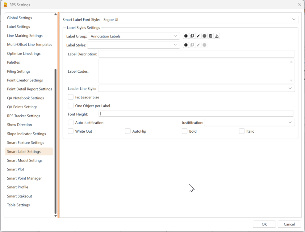
Smart Label Font Style
All Smart Labels will use the same Font Style for the text that is created. We recommend the use of Segoe UI which is a standard Windows True Type Font. We like this font because you can clearly tell the difference between characters like 0 and O and I and 1 etc. making numerical values easier to read on drawings. The font is also a True Type font so it looks polished on final drawings.
Label Style Settings
Label Group
Select the Label Group, Copy a Label Group, Rename a Label Group, Delete a Single Label Group or Delete All Label Groups or Import Labels and Label Groups from a spreadsheet.
Our default label styles are all in the downloadable spreadsheet shown below. If you are planning to define a lot of your own Smart Labels, we recommend defining them in the spreadsheet, so that you have a master copy, and then import them from the spreadsheet as needed. The spreadsheet is a template, use the same structure and key words for all labels. Most of the TBC Smart Codes are defined in a label already, this makes it easy for you to copy those and create new labels with different label content.
Smart Labels - Master.xlsx (43.7 KB)
Label Styles
Select a Label Style, Copy a Selected Label Style, Rename a Selected Label Style, Delete a Selected Label Style.
Label Description
Provide a more detailed description of the Label Style
Label Codes
Define the Smart Label using a mix of Text and Smart Codes. For detailed information on Smart Text Codes, refer to the attached spreadsheet or the TBC Help - search for Smart Text Codes.
Leader Line Styles
Select the Leader Line Style for this label from the Line, Spline, No Line, Line with Arrow, Line with No Arrow optrions.
Fix Leader Size Checkbox
When this is checked, the leader line geometry will be defined when creating the frst label of a sequence. It will then be reused on every subsequent label of that type until you either change label, or click the refresh button next to the checkbox in the Smart Label dialog.
When this is unchecked, the leader line for each label will be defined by the leader arrow point and the text label insertion point location, each leader will therefore be unique, but provides for a less formal labeling on a drawing, and also a more flexible location selection when a drawing carries a lot of detail.
One Object per Label Checkbox
When this is checked, a new reference object will be requested after the previous label has been placed i.e. the command loop will be select object, select text location, select object, select text location etc.
When this is unchecked, a reference object will be selected once, and then multiple labels can be placed sequentially i.e. the command loop will be select object, select text location, select text location etc.
Font Height
Define the Font Height for the label in Sheet Units (Inches or mm)
Auto Justification Checkbox
When Auto Justification is enabled, when you are drawing text labels with a leader line, if the leader line is created to the Right of the object / reference location, the text label will be Left justified. When the leader line is created to the Left of the object / reference location, the text label will be Right justified.
When Auto Justification is not enabled, the Smart Text Label will be given a default justification using Top, Middle, Bottom, Left, Center, Right justification options.
White Out Checkbox
When enabled, the text label will be drawn with a white background. The white background makes it easy to see and read the text when placed on a solid color background e.g. on top of an aerial photo, a cut fill map, a PDF file page, a solid object, a Smart Feature area etc.
When disabled, no white out is applied
AutoFlip Checkbox
When enabled, the text label will automatically invert so that it is still readable when drawing it parallel to a selected line would cause it to be upside down, or when text rotation is applied that would make the text upside down.
When disabled, the text labels are allowed to be right way up or upside down depending on where they are drawn.
Bold Checkbox
When enabled, the text will be bold on the drawing
Italic Checkbox
When enabled, the text will be in italics
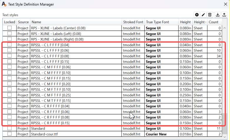
Text Styles for Smart Labels will be automatically created and can be reviewed in the Text Style Manager. The Text Styles created are all named in the same way, and are derived from all of the parameters defined in the RPS Settings dialog.
OK
Click OK to accept all changes made, and return to Smart Label
Cancel
Click Cancel to reject all unsaved changes, and return to Smart Label
Command Hot Keys
While using the Smart Label command, the following Hot Keys can be used.
Note that the alignment functions require the label to be visible, and that means that you have to click in the text location field to be able to see the text prior to placement. Note that some text labels are automatically placed e.g. text at centroids of polygons, so you have to click in the text location field, set the rotation and the size as required, and then return to the line select field to place the text in relation to a selected polygon / closed line.
Note also that if you have multiple TBC graphics windows open (Plan, Profile, 3D etc.), the line that you are trying to align the text with needs to be in the active window.
| Hot Key | Function Description |
|---|---|
| Hover over a line segment and | |
| CTRL | Aligns Text to the line segment |
| SHIFT | Aligns Text perpendicular to the line segment |
| Arrow Keys | |
| Left Arrow | Rotates text in steps anticlockwise around its insertion point |
| Right Arrow | Rotates text in steps clockwise around its insertion point |
| Up Arrow | Increases the text height in steps |
| Down Arrow | Decreases the text height in steps |
Apply Button
Most of the predefined labels shipped with Smart Label will be automatically created when you select the text location or click the reference object e.g. when adding text with leaders or free text or text that defines the area and perimeter of a closed polygon. The apply button is there as a catch all should you need it.
When you tap apply, the command will create the text and leader objects and then loop to start another text creation process. If you do not want to make a second selection and repeat the process tap Switch Command - Close to finish the process and close the command.
Switch Command
The Switch Command button provides the ability to Close the currently running command, close all running Smart Suite commands, or to switch from the current command to another command that is also running. You can also access the Switch Command list by pressing the ESC key on your keyboard, this will open the Smart Switch list of running commands right by your current cursor position.
You can also select other commands to run from the header bar icons in the current command dialog, or by selecting items from the Menus or RPS Navigate radial menu function.
Use Case Videos
The following videos show the use of the Smart Label command in a work process context
Feedback and Enhancement Requests
If you would like to provide feedback on the use of the Smart Label Command or to request enhancements or improvements to the command please click Reply below