Smart Elevate - Home - Click Here
Smart Elevate - By Points Mode
Command Function Overview
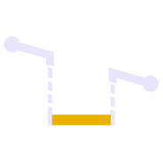
The By Points mode of Smart Elevate allows you to elevate a selection of lines using 3D points that lie on the lines or in close proximity to the lines selected.
When doing data prep, it is sometimes faster to create 3D points at all the locations where elevation call outs are provided and then use those points to elevate the lines, especially when the same points are used to elevate 2 or more lines that come together at a single location. You can use the Smart point command to create the 3D points prior to running the Smart Elevate - By Points mode.
Video Demonstration
The following video shows you how to use the By Points mode of the Smart Elevate command.
Command Execution Process
- Choose the spot creation mode - VPI or 3D node
- Set the offset tolerance i.e. the max allowable distance between the line and the points
- Select the lines to elevate
- Select the 3D points to use for the elevations
- Execute the elevate process
Command Details
The By Points mode dialog looks as follows
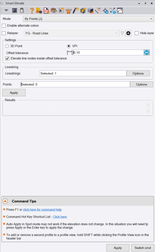
Mode Selector
Select the mode that you wish to use - in this case select By Points mode. You can also click J on the keyboard as the shortcut for the By Points mode.
Enable Alternate Colors Checkbox
This allows you to display lines that have currently undefined elevation in an alternative color e.g. Magenta. When you do this it is easy to see which lines have not yet been elevated vs those that are already elevated. When the lines become elevated as a result of using the By points mode, they change back to their native line colors.
Note that you can set up the way that this function works in RPS Settings - Global Settings as shown below - you can access RPS Settings from the icons in the command header bar.
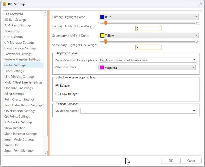
There are two alternative methods as to how you use the Display in Alternate Color function
- Display non zero in an alternate color - this displays anything that is 3D already in the selected alternate color.
- Display in an alternate color - this displays anything with zero or undefined elevation in the selected alternate color.
Depending on what you are doing, select the mode to give you the best solution to aid you in what you are doing.
Relayer Checkbox
If you are elevating imported CAD lines or lines extracted from PDF files, the lines are likely not on the layers that you ultimately want them on. You have two options here controlled by the above RPS Settings - Global Settings dialog.
- Relayer - this will relayer the selected and now elevated line to your target layer when you complete the elevating of the line and select a new line to elevate.
- Copy To Layer - this will create a copy of the source line, the copy will then be elevated and the copy will be moved to the target layer when you complete the elevating of the line and select a new line to elevate. Tis leaves the original 2D line where it was when you started.
Select the target layer for the relayering when the checkbox is enabled.
Hide Layer Checkbox
When you have a lot of lines to elevate, it is often beneficial to relayer the elevated lines to your desired layer for that type of line, but also to hide that layer so that the relayered objects disappear from the plan or 3D views.
In this way as you tackle each line, the lines disappear so that you know they have been completed.
Check the checkbox if you want to hide the target layer for the elevated lines.
Settings - Select Node Type
Elevations can be applied to lines as 3D nodes (defined as an XYZ coordinate), or as VPIs (defined by Station along the line and elevation). VPIs do not add a node in the horizontal geometry of the line only a vertical elevation control. If you add 3D nodes in the middle of an arc element, the arc will be split into two separate arcs at the 3D node location.
Select the node type that you want to use.
Offset Tolerance
The lines will be elevated using the selected points, provided that the points are within the offset tolerance of the line. The offset tolerance can be as large or small as you need it to be, just be aware that the larger the tolerance, the more ambiguous the result can become. If all the points are very close to or on the selected lines, then use a very small tolerance value.
Elevate Line Nodes Inside Offset Tolerance Checkbox
If the line being elevated has a 2D node in the horizontal geometry that falls within the offset tolerance of a nearby point, if you enable this checkbox, the node will be elevated by the point, rather than elevating the line at the nearest location to the point.
The points are computed in terms of Station and Offset to the selected lines, and the elevation location is defined at the station of the point on the line.
Typically enable this checkbox for this mode.
Linestrings
Select the lines that you want to elevate using the points. Note if 3D lines are selected, the points will be used to add additional elevations to the lines. If 2D lines are selected, they can be CAD lines, polylines, linestrings, rectangles, circles. All selected lines will be converted to linestrings during this operation.
You can use the advanced selection methods e.g. Select by Layer, Select by Elevation, Select by Polygon or Advanced Select by clicking Options.
Points
Select the points that you want to use or the elevating process.
You can use the advanced selection methods e.g. Select by Layer, Select by Elevation, Select by Polygon or Advanced Select by clicking Options.
Apply
Click Apply to execute the process and ready for a repeat process on a different selection of lines and points.
Switch Cmd
The Switch Cmd button provides the ability to
- Close the current command
- Close all currently running commands
- Switch command to another Smart Suite command that is already running.
Select the command or option that you wish to use
Note: The ESC key will also pop up the Switch Command list right on your cursor to save navigating to the command dialog to choose a different command.
Note: ESC ESC will close the currently running command.
Note: The ESC key will not work in commands like Smart Edit - Linestring Edit mode where the key acts as the toggle between Edit and Select Mode.
Header Bar Commands
In the header bar of the command dialog you will also find quick access icons to other commands that you ay find useful while running this command. the header bar icons act as a toggle switch if the command is already running (to make the selected command the current command), or will start up the selected command if it is not already running.
Header bar commands for the Smart Elevate command include the following
- Help (This document)
- RPS Settings
- PDF manager
- CAD Cleanup
- Smart Select
- Smart Draw
- Smart Edit
- Smart Model
- Volumes Manager
- Convert to Linestring
- Smart Point Manager
- Explore Object
- Profile Viewer (for linestrings)
Enhancement Requests
If you identify any defects in the command, would like to request enhancements, or provide any user feedback, please click Reply below.