The RPS Development Team has pulled together a great set of updates for this RPS command Library release.
I would like to shout out to Ethan Dowalter - the latest addition to the RPS Development Team - he joined us at the start of the Summer on an Internship - he has a computer science degree and is heading to Wyoming shortly to start his Masters degree - he had good experience in our industry and had used TBC during work experience at a large contractor in his home state in Ohio.
After just 13 weeks of coaching and tutoring by Peter he has been knocking out significant improvements to the existing commands in the library, adding increased consistency to some of the older commands and has even developed a new command all of his own! He has been fun to work with and we have seen a significant evolution over the short few months he has been with us - we hope that you like the changes / improvements he has been making. We wish Ethan the best of luck with his Masters - based on what we have seen - I am sure he will knock it out of the park! The door is open to you at RPS anytime you want to do some real coding!
The release includes the following
General Improvements
We have put a significant effort in improving the UI consistency across all of our commands by adding common UI elements where appropriate including
- Added the new Show Line Direction Control to all commands where the line direction is important
- Added command tips to the base area of commands to give you usage tips that assist your learning and remind you to press F1 for help where you can find full documentation for the command in use and a training video that shows you how to use all of the command functionality.
- Continued evolution of RPS Settings to support more command settings and UI controls. We have added sections for some new commands for Piling and QA workflows and addressed a bug that we found last week when someone deleted their RPS Settings folder by mistake - we now handle that gracefully! We also added improvements to the highlight colors controls allowing the primary selection line highlights to have their own lineweight.
- Custom Controls - further updates to our custom controls allow improved file selection and editing. You can now rapidly browse to the Current Project Folder, the RPS Settings folder or just Browse the PCs folder system to find a specific location.
- TMLStatus has been updated to open faster and allow you to get those updates installed quickly, allowing you to take advantage of all those productivity enhancements in double quick time!
Command Updates
Station / Offset Points Command
We have added the ability to create 3D points using Station, Offset plus Absolute Elevation, Delta Elevation or Slope from the alignment or reference line.
Reverse Line Command
We have added the ability to show the line direction markings on multiple lines at the same time, in addition we added the ability to set and display the line drawing direction based on the following new options
- Default Mode - This is the direction that the line was initially drawn
- Closed Mode - For closed polygonal lines, you can now set the line direction in clockwise or anticlockwise directions
- Reference Line Mode - Select a Reference Line or Alignment and you can then set the direction of the selected lines Towards or Away from the reference line, Forwards or Reverse of the reference line direction. If two ends of the same selected line are pointing toward the reference line, the closest end will determine the towards or away direction of the line.
- Uphill / Downhill - the line drawing direction will be either uphill or downhill with respect to the selected lines start and end point elevations. For multi segment lines, if they have up and down segments, the start and end point of the line are the only nodes that are considered.
This is now a great tool for checking / setting line direction to be parallel to the drawing direction (increasing station) of a selected reference line (Edge of pave, shoulder, sidewalk etc.) or to set line drawing direction toward the selected reference line (pipe laterals, driveway lines, lot lines etc.).
Best Fit Linestring Command
Now has a Layer control to place the created best fit lines on that has the New layer and Layer Filter controls also. We improved some error checking in the command to improve its performance.
Filter Line Markings Command
The command now has a multi-select control inside the command allowing you to select the lines to filter while in the command - this allows you to run multiple processes creating multiple selections that you can then use to relayer, join, change display properties or name properties etc. of the selected entities. This command is used to extract linear or cross section features from exploded solids, surfaces, component meshes or IFC Shell objects that are becoming more and more prevalent in digital data provided by engineers for projects.
Lock Views Command
The command now supports view rotation in either or both of the locked views allowing you to more easily track the data displayed in the two views when working with linear projects.
Surface to Grid Command
The command now supports both line and alignment objects as the reference line. In addition we now have the show line direction in the line selection control. The command has an improved command dialog, command tips, Help and Settings file access and it also uses the new RPS File Selector / creator control.
Create XLINES Command
The command has had a UI improvement to make the command easier to use. The alignment / corridor selector now has the show direction capability. Command Tips have been added for clarity and access to the command help documentation and video.
Point Detail Report Command
The command has had a UI improvement to make the command easier to use. The command now supports reference line or alignment and the show direction control. Command Tips have been added for clarity and access to the command help documentation and video.
Optimize Linestring Command
The command has had a UI improvement to make the command easier to use. Command Tips have been added for clarity and provides access to the command help documentation and video.
New Commands
QA Lines Command
This command has been created to provide QA capability for 3D lines and Pipes (utility networks). The command displays the lines slope direction, the slope % and color codes the arrows based on the pipe being between a Min / Max slope range tolerance defined. At a glance you can check slope patterns of selected pipes for gravity systems, slopes on sidewalks and ADA ramps, slopes on road cross sections and slopes / drainage patterns / birdbaths on curb & gutter lines. You can review the slope percentages and rapidly identify lines / pipes that fail to meet the minimum / maximum slope tolerances. You can also review line segment lengths and bearings if required.
Pipe Slopes and Lengths Review

Color code setup for pipe analysis

ADA Ramps and Sidewalk Analysis

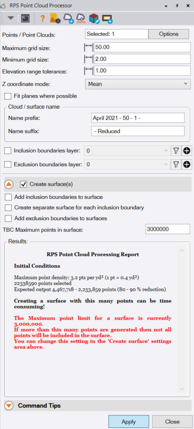
Point Cloud Processor
This command has been created to provide a fast and accurate method to reduce the number of points in a point cloud while retaining the accuracy of the final surface model derived from the point cloud.
You can select Inclusive and exclusive boundaries to limit the point cloud to site limits and exclude non surface areas (like tree copses, material storage areas, parking lots for vehicles etc.) and define a surface that will be created from the resulting point cloud including the ability to create one or multiple surfaces with or without hole or island boundaries.
The point cloud thinning process uses an RPS Proprietary binning algorithm that intelligently removes data in large flat or common slope areas while leaving points in undulating terrain based on smart tolerances defined by the user.
You can now take huge point clouds and thin them by up to 98% and still create accurate surface models from the resulting data. The Surface model generation is a bonus that eliminates the need to run additional commands to create the surface and then apply surface boundaries to add limits and holes into the surface model. The process also utilizes our new RPS Multicore Threading to spread the processing load across all available cores on your computers system, making dramatic improvements to processing times.
Point Cloud Processor dialog
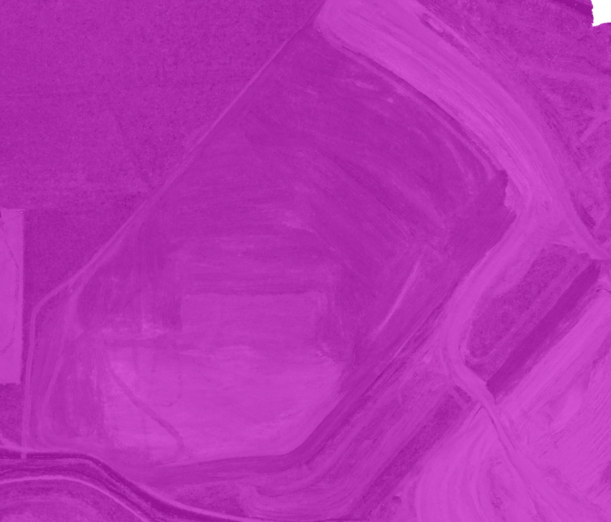
Point Cloud Before Processing ~22.4 million points
Point Cloud After Processing Without Tilted Plane Analysis ~741,000 points
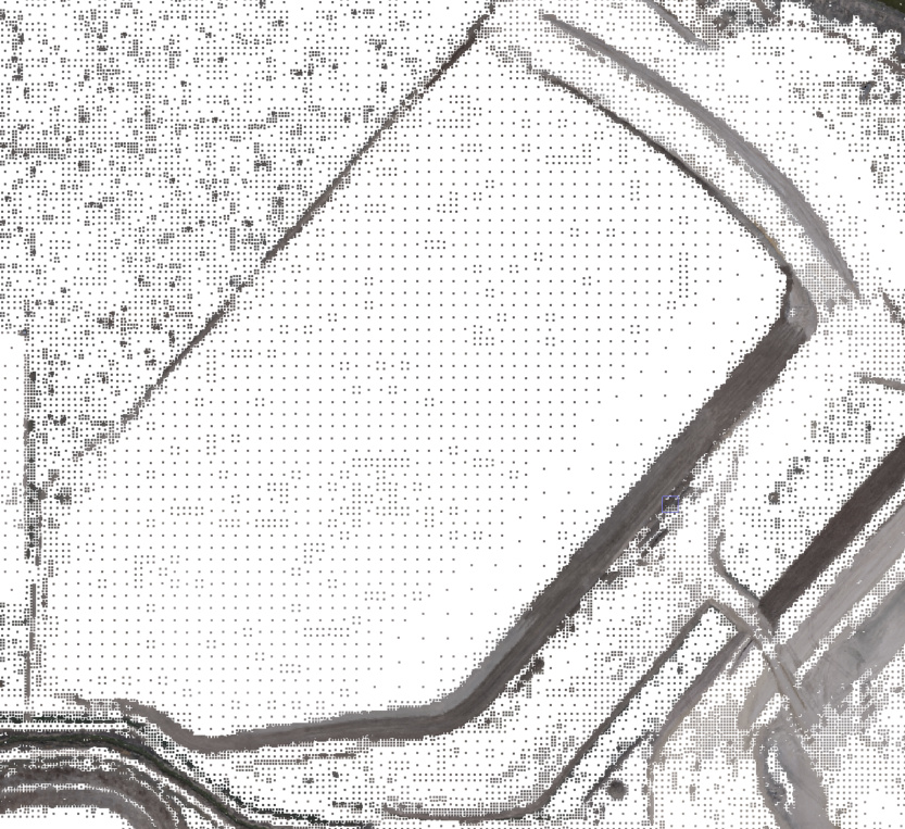
Here you can clearly see that with horizontal plane only analysis, large flat areas are heavily reduced by the processor, while sloping areas retain most of the source points of the original scan. Note also the colors of the source points are also retained in the created point cloud scan.
Point Cloud After Processing With Tilted Plane Analysis ~412,000 points

Here you can see that with the additional tilted plane analysis, the sloping areas are now also heavily reduced in point count and point density.
Results Analysis Pane

Once the processing has completed, the results analysis pane will show the processing results and list any areas that failed to meet the processing tolerances - you can double click those failures and the graphics (plan or 3D) will take you to that location in the model directly for review purposes.
3D View of Reduced Scan Surface Model
Here you can see that the resulting surface model from the reduced scan

Note that the scraper cut tracks in the surface can still be seen in the surface created from the reduced scan, and all features of the project status still remain. The surface while the point count is heavily reduced, will still generate extremely close volumes to a surface created from all 22.4 million points. The surface is smoothed by the tolerances used - this has the effect of filling in some holes and shaving off some areas, however the balance of cut / fill will be close to a zero balance. Using tighter tolerances results in the retention of more points in the created point cloud scan.
Pile Definition Manager Command
The RPS Piling tools are designed to supplement the TBC Piling tools and utilize the TBC Pile Objects and Pile Plan Objects. The commands have been developed primarily for Solar Farm construction applications. The tools have been developed to support a wide variety of design, QA and Survey QA data in line with user requests.
The Pile Definition Manager creates the pile definitions using the color coding systems that are commonly used in Solar Farm construction. Colors are used to define the different length and cross section areas of the steel H piles used to support the solar racks and motor units. You can create different pile definition settings files to support different projects with different requirements. The pile definitions are used by the Pile Plan Design importer command (see next command).
Import Pile Plan Command
The Import Pile Plan command provides a user definable means of importing pile design information from Excel Spreadsheets. The command allows the user to define a template for importing a specific excel spreadsheet data stricture - the format definition maps a column of data in the spreadsheet to one of a selection of Pile properties including Pile Plan ID, Pile ID, N, E, Z (top of Pile), Pile Color etc. The import templates can be created and stored as RPS Settings files for reuse on future projects. The importer can now import thousands of piles and create Pile Plans, color coded piles, pile points for staking, QA or robotic layout in just a few seconds. The resulting data is 100% compatible with Trimble Groundworks.
What’s more? The importer also includes our new Rules based import functionality, allowing you to define a column of Rule Trigger fields e.g. Dead End piles that have the text “Dead End” in column “N” are used to rotate the pile by 90 degrees and to change it’s design elevation by -1’ to further automate the import process.
The command also provides a similar set of tools to import machine generated QA data to create the As Built Piles that can be directly compared graphically with the Design piles.
The command also provides a set of tools to import survey data points that QA the top of pile.
The Design, As Built and Survey QA data are then used in combination to generate the Pile QA report (See below)
Pile QA Report and Output
The Pile QA Report takes the Design Piles, As Built Piles and Survey QA data and analyzes all of the piles against 6 QA checks to build a 6 tab Excel spreadsheet report that analyzes and reports all of the piles with respect to each QA Check. The process also creates a set of QA points - one for each pile that carries all of the error analysis results for that pile that can be output to GIS formats for GIS database use in e.g. ArcInfo or ArcPad (field product). The QA metrics that are checked include
- Position check (XY and 2D)
- Alignment check (piles align within tolerance)
- Vertical Alignment check (pile tops align vertically)
- Twist check (Pile is rotated N-S, E-W within tolerance
- Minimum Embedment / Reveal check
- Verticality Check
- Overall QA Check