Good afternoon Rock Pile Team,
I am having issues terminating corridor sections for manual modeling at intersections and driveways. I am utilizing a single typical section, with “controller” nodes to initiate different shoulder treatments. I model the mainline of the roadway through the entire project, but switch back and forth with shoulder treatments or ?none? in areas of intersections and driveways as i will return to these locations and perform more detailed manual modeling. For some reason, when i terminate my shoulder treatment, the model is producing a breakline from the furthest point out in my corridor template back to the edge of lane. When i explode the surface, to check breakline names and confirm what is causing the issue, the breakline is not named, telling me it isn’t related to a specific instruction. I also thought it may be related to side slope instruction, though they still appear when i remove the side slope instruction.
Hoping you can help explain;
-What is causing the “exterior” breakline to generate?
-What is the preferred workaround to force a smooth termination of the shoulder treatment typical?
Thanks in advance,
Joe M
When this comes up in my corridoring, it seems to be due to a tiny bit of overlap longitudinally in the surface.
To mitigate, I terminate the instruction at the last triangle before the transition.
it’ll put a tiny gap in your corridor, but it is negligible.
hope this helps
1 Like
One thing to try is. At the instruction that is having the issues with the overlap triangle. Step back the end station by say 0.02’. That way it stoped before the before the jog out.
Thanks for the response guys! That definitely works “most” of the time, and is often how I also work around the issue. But as my single template, conditional corridors get more intricate, it winds up leaving me having to apply these annoying little fixes to a rather high quantity of instructions, all the more easier to accidently modify the wrong one.
I’m hoping Alan and the team might have an idea why this “outer surface break line” (that doesn’t correlate to an actual node code) exists, how it works, so I might be able to completely move away from the small table terminations spread out through my instruction list.
Thanks again!
Hey Joe,
Can you send me your project file so I can take a look at your data? My instincts would say that it is probably caused by non-tangent bearing deflections in your alignment but I wouldn’t be able to say for certain until I look at it.
1 Like
Shane,
Brilliant. Your instincts are 100% on (sent corridor in a message)! The alignment is of an urban design where tangents fall between street intersections with horizontal deflections in each center. So I can imagine there a few ways to go at this, what would be the best approach to maintain a single alignment, single template, through circumstances like this? Does this behavior only occur once triangles overlap (or does it trigger automatically regardless when you have a horizontal deflection in the alignment)?
Can I add a controller for the template as a whole, and null through the H. Deflection? Or will I be forced to break up the alignment?
Thanks for taking a look!
Joe M
Hey Joe,
So… Looking at your file I would say there are a couple of factors at work. One of them would be as I mentioned earlier with the non-tangent breaks in your alignment. These can be handled in a number of different ways.
-
If this alignment was created from the cad line that seems to follow the created alignment you could run “Convert to Linestring” on the line and use the reduce horizontal node option to strip out unnecessary horizonal vertices in the line before creating an Alignment from it.
-
I would look at the alignment in the plans to see if the true alignment has these non-tangent deflections as they may be part of the overall design. If this is the case you could separate the road into multiple corridors stopping just short of the non-tangent break .02 or.03 in stationing. Then start an new one on the other side of it. Alternatively you could do it in one corridor with new template drops that are not allowed to transition using the same practice as the new corridors but your template drop effectively becomes the new corridor.
-
If the alignment in the plans does not show these non-tangent deflections you could manually input the alignment to insure it matches the plan geometry. Or you could get the alignment from the designer in an xml format and import that xml.
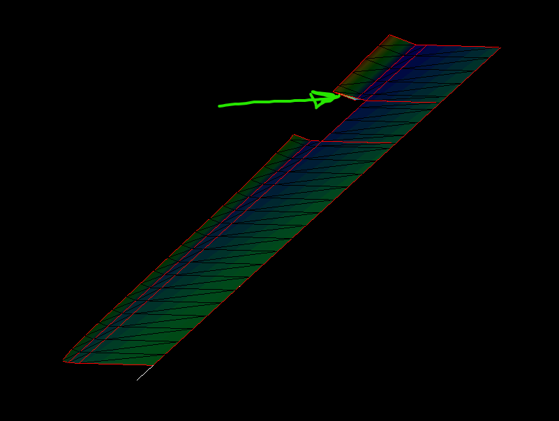
The other issue that I am seeing as relates to your picture and looking at the corridor around station 27+93. This transition issue seems to be tied to your table transitions and the methods described by the other users in this thread would rectify the issue. Alternatively it appears that you have 2d linework for much of what you are trying to do with your tables and conditions. You could replace your table’s numerical offset values with the appropriate 2d line control. This could potentially replace your need for the conditions or reduce the number of conditions needed on the corridor depending on what you are trying to achieve.
Let me know if that helps or if you have any other questions.
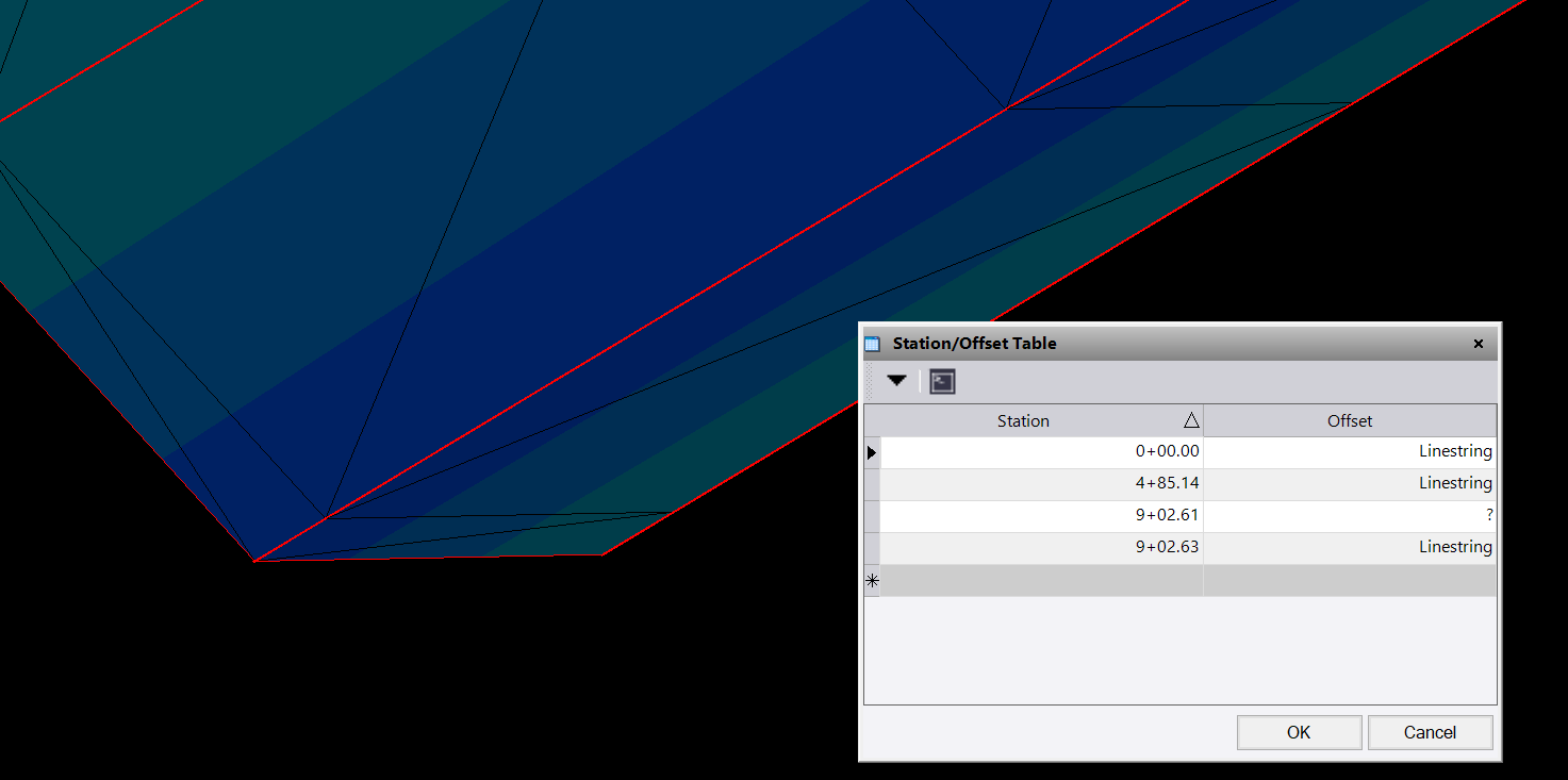
One thing you might try to alleviate needing to add “?” to every table is to drop a X-Line a couple hundredths back on station and then trim your linework to the x-line. then your linework wont extend beyond the centerline station and will stop because the linestring doesn’t exist there.
1 Like
Interesting… as you mentioned, i have a lot going on in the provided corridor. I have made an attempt to uncomplicate the corridor and still show the issue (see attached vce)
2024-03-25_RevCorr.vce (3.8 MB)
.
- I removed all “allow transition” check boxes
- I entered a false alignment which consists of a single tangent, straight alignment without deflections
- I removed all tables (with exception to my “controller” table). This is essential, for me to be able to run a complex corridor, without many typicals.
- I was concerned also that the Side Slope instruction was causing the issue, so i added a different instruction in it’s place, and it still happens.
Best i can tell, it must be caused by one of two things:
- My template transitions from one instruction to multiple, in this case through a condition.
- something related to my “controller” conditional definition
I am praying there is a way to do this with a “controller” conditional…
Let me know your thoughts.
Thanks,
Joe M
Hey Joe,
I recorded a video looking at your new file, I figured it might be easier than hitting you with another wall of text. let me know what you think.
1 Like
Hey Shane,
Thank you so much for the video and taking a look, it really has been a great help. Sorry about the the last VCE, stationing didn’t line up well, it shifted when i made a fake alignment.
So, technically there isn’t currently a plan set, I am in the process of designing it. I do road design for my day job, and build machine control models on nights and weekends :). In regards to the alignment, i have some historic data and stationing i will be married to, but can work around the non-colinear issue. I think you discovered the root of the problem, that is my conditional “controller” or “decision” node.
I apologize, i should have explained my thought process a bit. So the floating node 2>LSHLD_DEC is my Decision node. Basically i assign multiple shoulder typical to numbers(examples 1.0, 2.0, 3.0). In this instance 1.0 is a class II shoulder. Inside the Decision Node, i add stationing that i want 1.0 to apply and terminate with a ?. Then in the actual instruction i state, if that floating node is 1.0 ft horizontally from centerline, then build this type of shoulder. It is a way that i can have multiple shoulder treatments at my disposal, and control them all in one place.
Ultimately I would like to move away from the option of adding in small gaps in the side slope instruction. I have modeled projects that had 50+ driveways/intersections, and it gets messy and difficult to track in the table(s) at that point. I also would like to use a sharable slope table, and use it to transition slopes across some of these locations. This gets difficult to do as then i have to start pro-rating side slopes at each individual break.
It is odd that the corridor creates the double section and gets out of perpendicular to the section due to the “controller” or “decision” node. You did drive a good point though, that i may be over complicating the approach. I could still split my shoulder typicals up as i have, and only turn them on through the use of line work in the table. It does require a table for each shoulder typical, but if it will work properly, it is a fair trade off. I’ll have to do some pondering to re-think my approach with the use of linework in mind.
Thanks again for taking a look!
Joe Melchiori