In the video below we show one approach to modeling the toe of the side slope of a pond that is often missing in the Engineers plans.
Ponds are often displayed on the plans as Design Contours and while they tell you the intended slope of the pond side slope, which may be constant e.g. 3:1 or as in this case the side slope is also variable along the length of the pond slope (whether by “Accident” or “Design” I don’t know) it typically lacks a line showing the actual bottom of the pond slope where it meets the design base.
In the example we have the pond contours for the slopes and we have one contour on the base of the pond and in the plans it calls out a slope of 0.6% away from the base contour in two separate directions. They also give us a pond outlet that has a known elevation at middle of one pond edge. If we compute the slope from the drain outlet to the contour it shows the slope is 0.57% not 0.6% so the question starts - is the slope 0.57% and it is simply rounded to 1 decimal place on the plans, or should it be 0.6%. Over the 150’ to the pond edge (max distance) that difference of 0.03% is 0.045’ so do we care about 4/100ths or not?
I go with the label on the plans in this case but my gut tells me the 3D elevation data they provide is possibly correct or the contour is off slightly - that is one for the engineer to solve if you are not sure.
The video shows how you can use a combination of the RPS Slope Designer command along with some of the standard CAD Tools (Break, Trim/Extend, Join) to create a base surface for the pond, and then use the Side Slope command to compute the toe of the pond slope allowing for the variable side slope around the pond (if that is indeed correct).
Hopefully you will find the video useful
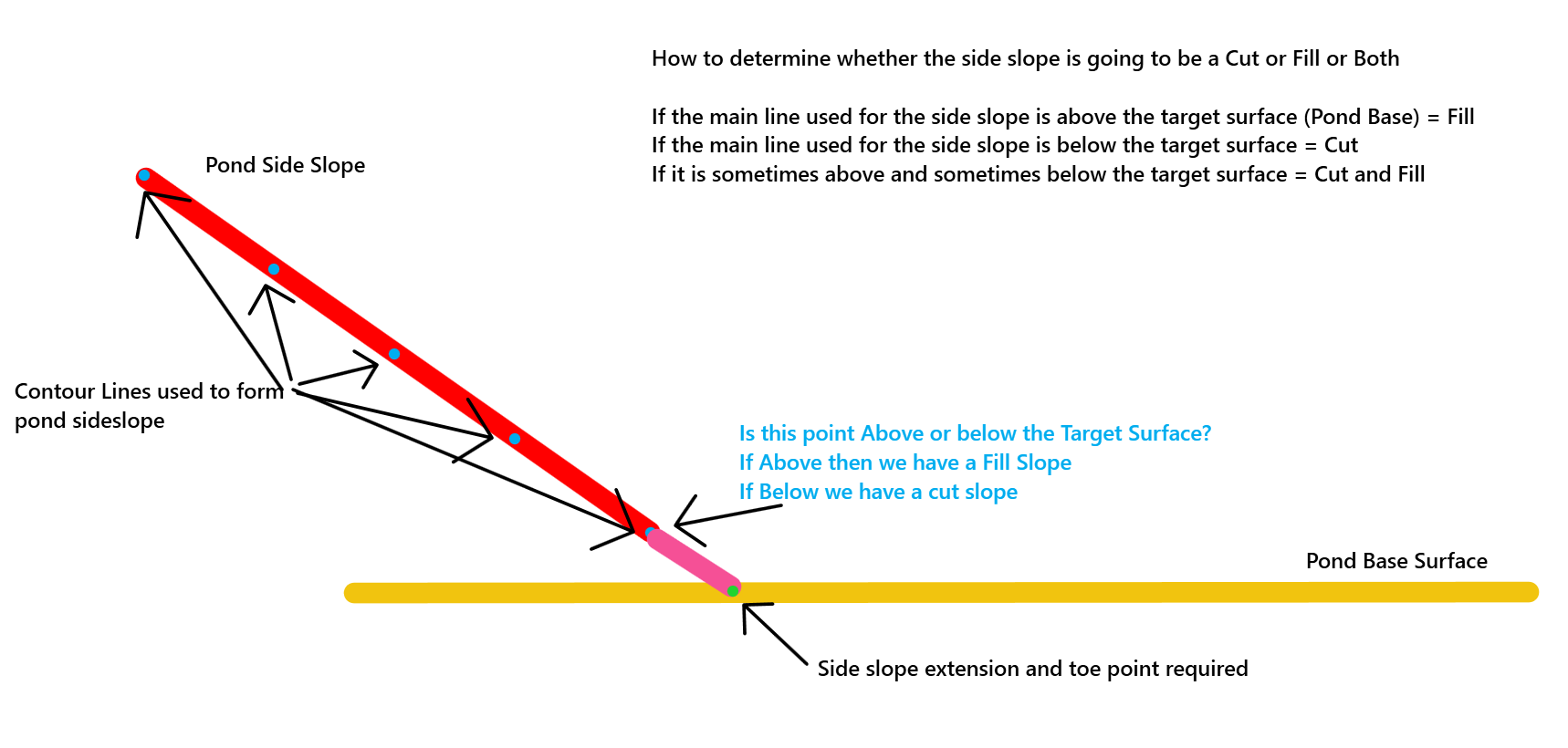
How to determine if the sideslope command - side slope instruction should be a Cut or Fill slope
How to set the direction of the Side Slope instruction
If the first instruction coming off the line used for the sideslope path is a sideslope instruction, the command does not know whether you are asking it to project to the left or right side of the source line if you select “Auto” so select Right or Left depending on which way your line is drawn (clockwise or counter clockwise etc.). If you have an instruction in the sideslope template before the side slope instruction that e.g. is an Offset to the left or offset to the right, then the Auto mode assumes that the sideslope direction is the same side of the line as the previous instruction, i.e. if the previous instruction is to the Right then the sideslope will also go to the Right. In most cases this is correct, however sometimes a sideslope can point towards the centerline from the right side etc. (divided highway with median ditch or median slope. If you cannot get an instruction like his to work, put an offset slope instruction immediately prior to the side slope instruction that is pointing the way you want to go with an offset of 0.01 and a slope of 0%. This trick will set the sideslope off in the right direction.