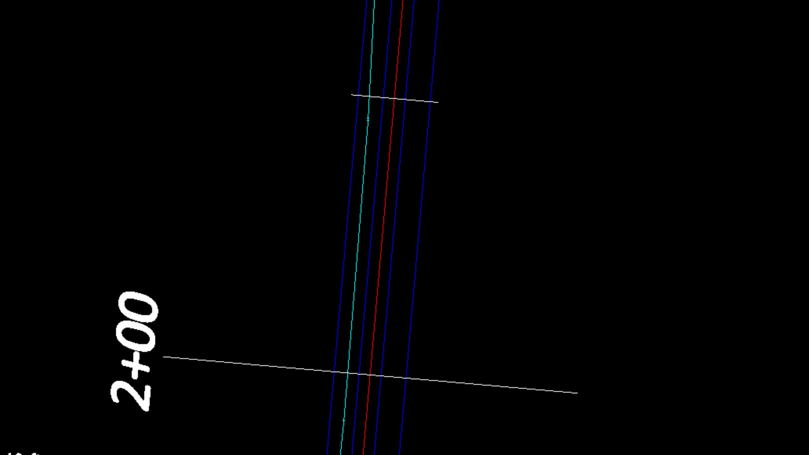
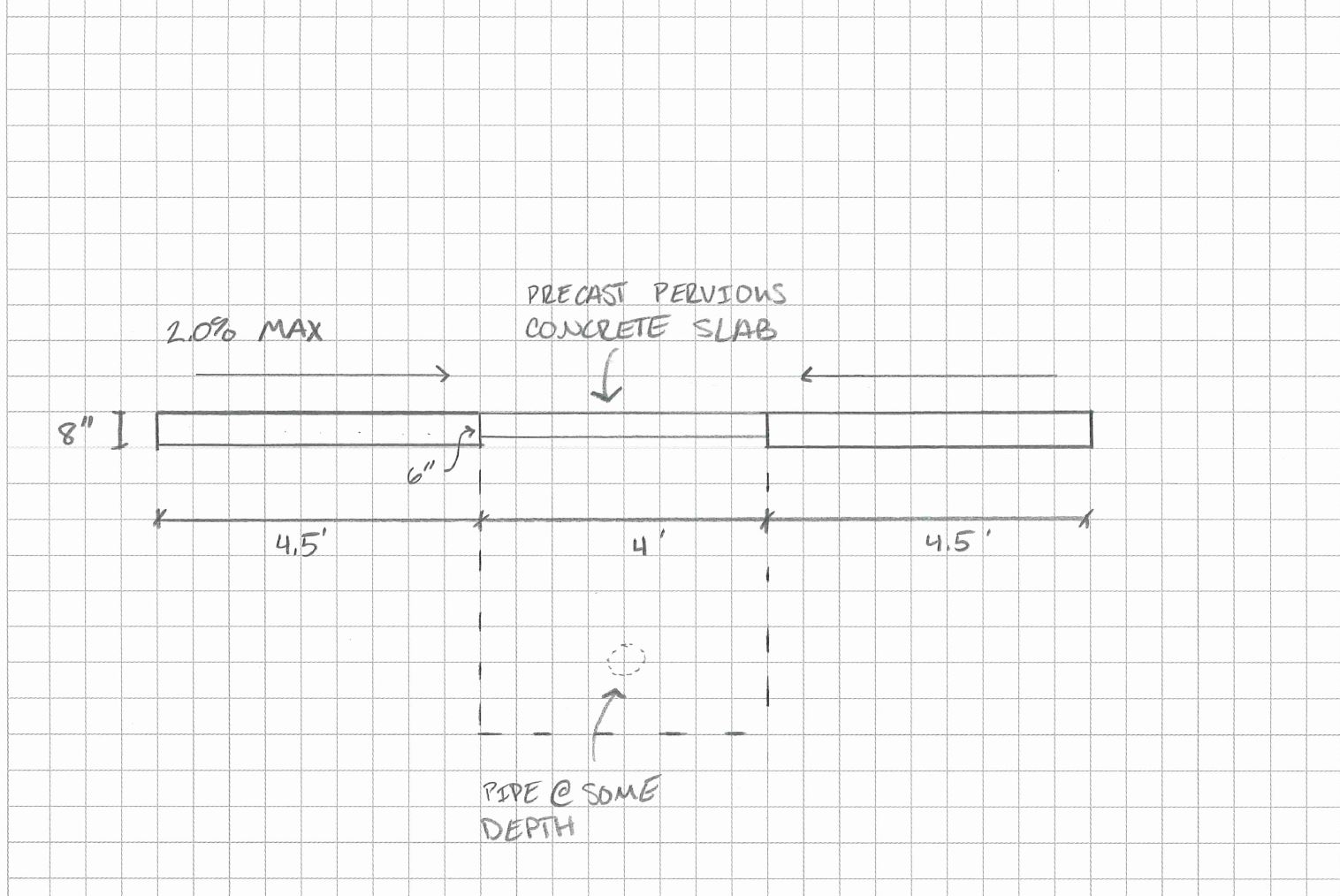
I am currently working on a project paving some alleyways between houses in New Orleans. It is basically a design-build project and I need to submit some cross-sections to DPW for their review. The cross-sections are not complex at all, as I only need to show the finished surface, proposed drainage, and the location of a gas main. I don’t have a lot of experience with cross-sections and I am having trouble getting the gas main and drainage to show up in my sections. Both the gas main and proposed drainage run linearly down the project. I have selected both 3d lines as reference lines in my corridor, but they still don’t show up. I have included a couple of pics that might help understand. The cyan line is the gas main and the red line is the proposed drain line. The drawing created in MS Paint is how I would like for the lines to show up and what information I need labeled. Any help would be appreciated.

Jim
The way to label the Gas Main and Water Main with the difference to Finish Grade Surface is as follows.
The key points are
- Select your utility lines and add them as Reference Lines to your Corridor Model. The line locations will then be usable for the placement of Node Labels in the Cross Sections.
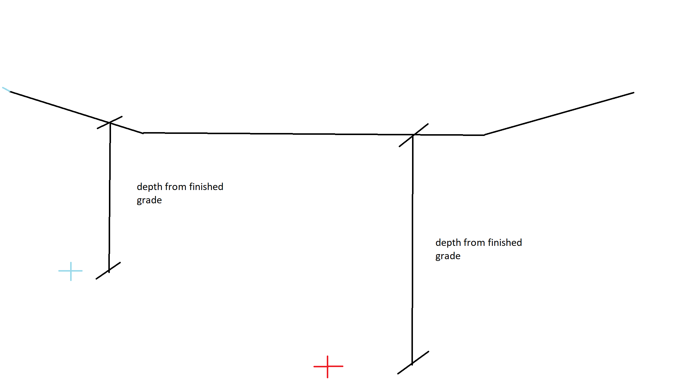
- In your Cross Section Sheet Set - you will need to use the Editor to add Node Labels for your Utility Lines. If you want to label the difference in Elevation between the Finish Grade Surface and the Utility Line (at the location where it is defined (Crown, Invert, etc.) then you will need to use the formula shown below in your Node Label “Label Field”
Note that you need to use this formula in the Node Label where I show it in the video - this computes the difference between the Finish Grade and the selected Utility Line
|-{diff,[[Finish]{z,3}],[{z,3}],2}
The video shows how to do this
Here is my project if you need it as a reference
2 PGL Road with Supers and Rollovers.vce (718.6 KB)
Hope that this helps
Alan
1 Like