We have a big project where the general contractor is effectively using common access to a BIM360 coordination model as the primary authoritative design data. I find myself having to work from IFC data frequently modeling for this site, without backup from paper plans.
Footing excavation models from concrete IFC models have worked like a charm, but what’s been difficult is the pipe. There’s a massive model with thousands of elements for electrical and communication conduits under the building, and for excavation purposes all I need is grade and width for trenches containing whole banks of conduits.
Exploding the conduits via IFC Explode generates 300k+ linestrings, and all I’m interested in are the single linestrings representing bottom center of pipe. Using the Normal Down option still generates 160k linestrings. Is there any way to add a feature to this command to generate only the bottom centerline of pipe structures? Carefully selecting only these has been a lengthy and painstaking manual process.
2 Likes
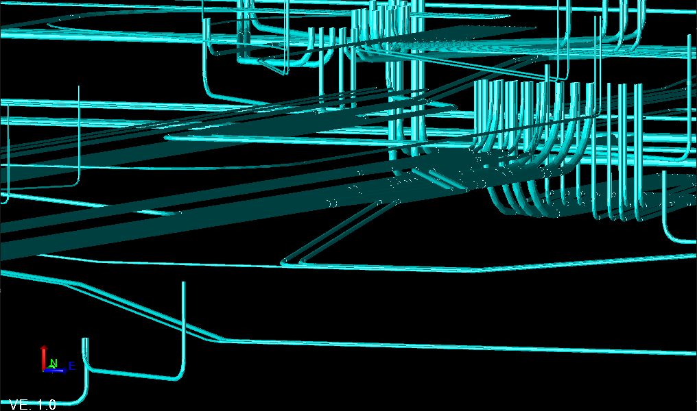
For example, in this screenshot I’ve selected the unwanted linestrings for a short run and the number of unwanted is close to 2000 linestrings. This is with only the bottom of the IFC structures exploded (bottom half of pipe).
1 Like
Did you happen to find a better way yet? I have a project with this exact same scenario. And the way you explained it as above is how I’ve done it in the past. Not sure if there is a better or faster way…
2 Likes
Arron, there still isn’t a better way that I know of- we were just digging trenches for these duct banks, so I ended up free-handing a 3D-linestring along the approximate center of the bank trying to capture the bottom profile accurately, and then free-handing a pair of 2D guidance lines for either side of trench so the machine operator would know how wide to dig. Then they just followed the 3D line for grade much like they would for a pipe model.
The good news is that Alan reached out to me last week (maybe he’s been in touch with you too) about developing something to address what I described in this post. So stay tuned.
1 Like
Thanks! What you stated above was exactly what I did as well for the time being.
Are you working on Data Centers by chance? I’ve had this same exact issue on the project I’m working on. In your BIM Model, do they have the actual duct bank modeled? We ended up using that instead of pipe centerline to create machine control designs.
I have recently just exploded the pipes and choose VT only. It creates some lines around the exterior but not all the way. I still have to go through and pick the bottom but it is easy to see. I just re-layer those afterwards and deleted the rest all at once. Only will go half way around so it really isn’t that bad to clean up.