I have an issue where I have a number of edited surfaces that I want to form into one overall composite surface using the surface hierachy to dictate which take precedence. I am finding that the breaklines that make up the original surfaces are ignored in the resultant composite making it pretty ugly. This occurs whether or not there are surface overlaps. Any suggestions as to why this may be happening?
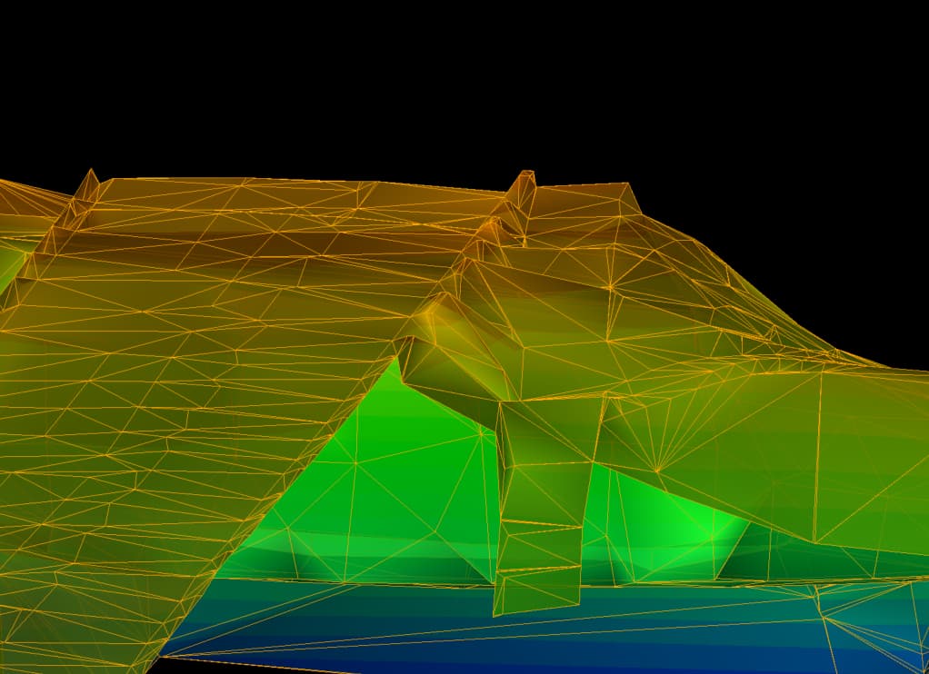
This is the original surface made up of source objects
and this is the composite
Mark
Send me the file and I will take a look
Were the original surfaces subgrade adjusted surfaces or were they made from points and lines - i agree the result is not pretty - i am wondering if it supports real breaklines in the surfaces but not internal breaklines / drapelines.
If i can get the data I can raise the issue with Trimble since thisnis one of their commands - if I can find a way to work it I can report back to you.
Alan
Thanks Alan and Chris for your prompt response. I will try to answer your questions and also get you up to speed with my experiments this morning! I have attached the ttm surfaces which I need to make up the composite.
For some background, the contributing surfaces have been made up in various ways.
“01 Rutherford ttm” was made up from source data direct from a total station ground survey.
“02 Adjusted Grass Areas Combined” is a combined surface made up from LiDAR data which was then split into separate areas and an “Offset Surface” by different amounts applied to these individual areas.
“03 Draped Surface Boundaries” is a surface created from the same LiDAR data but left at original level. The 2m boundary separation is an attempt to get rid of the step caused by merging surfaces.
“04 AShaw MSSB Hard Data ttm” is made up of source data direct from total station / GPS survey.
“05 Riverworks Cleaned ttm” is more LiDAR data with rogue high / low spots removed.
It makes no difference if I import the .vce file of the surface which includes the source data as opposed to the .ttm file of the same surface.
The prefixes 01 to 05 are the order of classification in the composite surface with 01 being on top and 05 being on the bottom. It can be seen however, that 01,02 and 04 are individual and don’t overlap with each other. It’s only 03 and 05 that need to be overwritten with the surfaces above. All the surfaces are actually substantially larger but the attached pinpoint the main areas where the problems are obvious as ringed in blue below.
A couple of observations from this mornings experiments. Leaving out surface 05, if surface 04 is above 03 in the hierarchy then I have issues with breaklines, even though they don’t overlap at all. Once I move 04 below 03 then it is fine. This in theory solves my problem until I add surface 05 into the mix which then throws it out again.
I hope this all makes sense. I could be doing something dumb somewhere along the line so another set of eyes would be helpful. I can supply source data if you think that would help.
Many thanks
Mark
04 AShaw MSSB Hard Data ttm.ttm (84.3 KB)
05 Riverworks Cleaned ttm.ttm (197.5 KB)
01 Rutherford ttm.ttm (8.9 KB)
02 Adjusted Grass Areas Combined ttm.ttm (81.9 KB)
03 Draped Surface Boundaries ttm.ttm (82.2 KB)
Mark
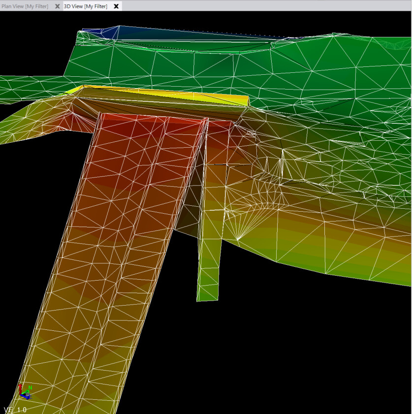
I have just followed your steps in 2023 and it appears to work better in 2023 than you are showing in your screen shots - here is the composite surface that I built with Order 1,2 4,3,5
And with Order 1,2,3,4,5
So I am guessing that Trimble fixed this up some in 2023
Alan
1 Like
Thanks for taking the time to look into this Alan. I will get on to upgrading to 2023.
Mark