In the video we show you how to import PDF Sections, how to review the data in them to develop the strategy / method with which to convert them and then the simple Data Prep processes to separate the data as needed for conversion.
Key decision points are
- What type of sections are these (No Grid, Single Grid or Multiple Grid) - These are Multiple
- Do the sections have text for Station Labels - In this case Yes
- Do the sections have text for Grid Labels (Elev and Offset) - In this case Yes
- Is the Offset Text individual labels or are they merged into a long text string - In this case Single Labels
These are all GREAT answers
Separate the Grids, Station Labels and Elevation/Offset Labels onto 3 separate layers and remove any other data that you do not want - these 3 layers have to be clean.
- What layers do I need for Existing, proposed and subgrades plus any other data that I may want to keep and flip eg Barriers, ROW lines, Walls, Utilities, Culverts etc. that may appear in the sections.
Separate these from the other data that you don’t need.
Lastly what is your use for the data when you get it into 3D - are you using it to model or are you using it to check your model i.e. query cross slopes or offsets or elevations etc. The more modeling you plan to do dictates how much time you use to separate the data out in the Sheet view prior to flipping the data into 3D - the more time you spend cleaning the data in Sheet view will typically save you the time in the 3D view once the data is flipped. However some things are easier to separate out in 3D view than in many sheets of data in the sheet view - that comes with growing experience. Use commands like relayer and Geometric Selection in Sheet View / Multi Sheet View to separate out the data. Mastering these two commands will save you many hours of work over the course of a year if you do this kind of work often enough.
If you want a single line for Finished Grade and or base of subgrade you can use the Track Cross Section command on multiple sheets at once to find the Top of Finished and the base of subgrade surfaces on separate layers - this can be helpful if you are building models.
Now the data is prepped - create an alignment to use as the reference for each set of sections and then flip the sections using the Create from CAD command (this works with PDF and CAD Sections in a similar way)
Video shows you how
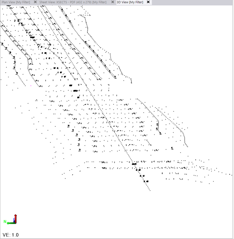
I then used Point Creator to create Points at the ends of every line / nodes of lines of all the sections - as discussed you can then Label those points and color code them if they are High / Low / On grade compared to the Design Surface if you want to find places in your surface that don.t match the section points. I did not have a ref surface so I could not do the Label Points command but I am sure you can work that out
Points
Then I analyzed the Points with Face Analyzer to create the Push Pins between the points and a subgrade surface
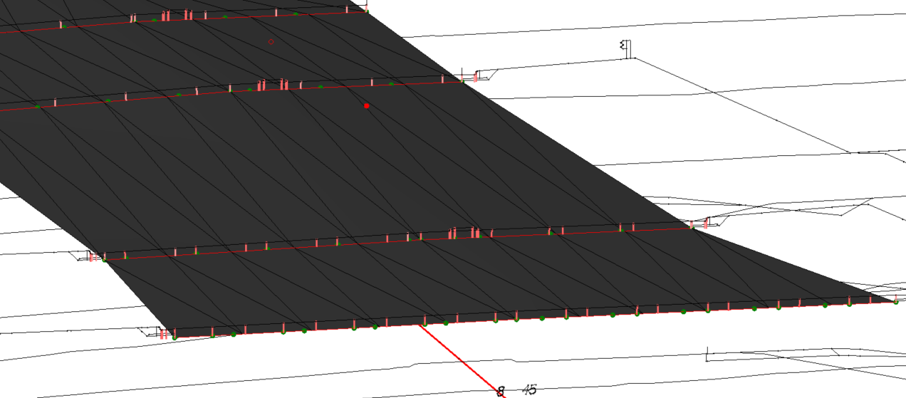
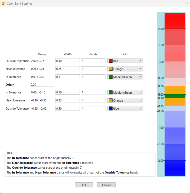
The length of the pins is the delta to the surface model, the colors are derived from the Color settings
If the pins are going to be very short you can add extensions so that they stand out more.
Alan
Alan