This question came in today and I thought it was worthwhile capturing a video of work processes that may assist the process of designing a pond for a Gas Frac operation.
You have an Existing Ground Model
You have a delineated Gas Pad area inside which you need a storage pond of a certain capacity
You have an area within the delineated area for the pond
The pond design will provide balanced earthworks and the required storage capacity, and the earthworks need to fit inside the delineated area for the pond.
You want the top of the pond to have some of designed regular shape e.g. a rectangle with curved corners or a rectangle with angular corners.
The pond will have some design criteria - the top of the pond berm is used as an alignment and on the outside you need a sideslope to existing ground at a defined slope e.g. 3:1 (cut or fill slope). On the inside you want a berm width e.g. 10’ flat top and then a slope into the pond of e.g. 2:1 that provides a minimum depth of water of e.g. 15’ and a 2’ clearance from high water level to top of berm i.e. a 17’ elevation drop at 2:1 slope. In some designs because the slope is 2:1 you need a bench 10’ wide at 2.5’ depth below max water level for safety that will arrest someone from falling into deep water.
When you know the design criteria then you can start to work out the design to provide the necessary pond volume and the berm elevation required to provide a Cut / Fill Earthworks Balance. Then you can iterate your design to move the pond so that it fits inside the delineated area, change the shape of the pond to make it fit and to maximize the storage volume, and change the elevation of the pond so that you balance the earthworks and if necessary deepen or shallow the pond base to increase or decrease the storage capacity.
In the video we show you
- How to create the pond shape and how to manipulate its position using the Move command and how to manipulate its shape using CAD Grips and how to manipulate its elevation using Change Elevation command.
- How to define a Sideslope model for the pond design
- How to define a Sideslope model for the Max Water Level Surface
- How to add a Sideslope object to a Surface Model to create the Pond Surface and the Max Water Level Surfaces
- How to create Cut Fill Maps between the Existing Ground and Pond Surface (Cut, Fill and Balance for Earthworks Operations) and between the Max Water Level and the Pond Surface (Cut Volume = Pond Capacity).
- How to create smart text blocks that show the Pond Volume Capacity and the Earthworks Cut, Fill and Balance quantities. We show how the Smart Text dynamically updates to show new values as edits are made to the pond shape, position or elevation.
Smart Text for Volume of Pond Water
This smart text displays in Barrels of water vs CY using a conversion of 4.808 Barrels to a CY
The object reference is the Isopach created in the Cut Fill Map for Max Water Level - Pond Surface and uses the Cut Value only.
Pond Volume
Capacity = @<OD,O,VC,F,2|*4.808>@ Barrels
Smart Text for Volume of Earthworks
The object reference is the Isopach created in the Cut Fill Map for Existing Ground - Pond Surface and uses the Cut, Fill and Net volume values of the Isopach
Earthworks Volume
Cut = @<OD,O,VC>@
Fill = @<OD,O,VF>@
Bal = @<OD,O,VN>@
Note: because the smart text is using the Isopach volumes, the Isopach gets updates each time either of the reference surfaces is updates thereby updating the Cut / Fill volumes or pond volumes with each design modification made.
Note:
I typically design ponds starting at the top outside edge of the berm - however if you have a sloping base of the pond then it is probably easier defining that as your reference for the sideslope objects.
I would still create a High Water Sideslope and surface but that may be a little trickier unless your max water is always at a fixed delta elevation from the pond base - if you know that you have a 3:1 slope off the pond base, I would design that into your starting linework up to the point where it is a horizontal closed polygon to take out the slope of the pond base i.e. start with the following base design
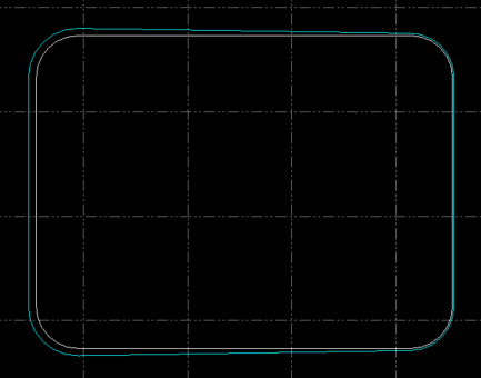
The Cyan Line is at a constant elevation whereas the white line has your 0.5% Pond Base slope going from East to West in this example. I then used Optimize Linestring on the Cyan Line to make it Curvilinear and then I would use that as my reference for the pond design and the High Water - assuming that High Water is a constant Delta Height above that line at your 3:1 slope - this way I can create two sideslopes from this line that gets me the surfaces I need for the computations.
In this case, if you know the depth of Water from Max Water Level to the Flat Base of the pond is e.g. 8’ then just create an offset line vertically above the pond flat base line and then offset that outwards by 50’ at 0% slope and use those two lines to create the Max Water Surface. Just remember that if you need to move the pond or change its elevation that you need to pick the 4 reference lines - the two pond base lines and the two max water lines so that the Max Water changes with the pond movements.
If you need the small pond in pond (the 50x50 area that is 2-4’ deeper than the rest of the pond, then also design that into the pond base. I would also make a selection set out of the Pond reference lines to make them easy / fast to select
Through this approach it is easy to rapidly design the location, elevation and shape of the pond that meets the design criteria, and provides you with dynamic models that update in line with changes to pond sectional shape e.g. Depth, slope, elevation deltas, offsets i.e. you can narrow the Berm width, change the pond depth, quickly and easily to refine your model as you iterate towards your end goal.
Hope this helps