What set of instructions will allow for the ditch depth variables to create a corridor surface that matches the detail. The height of the back slope of the ditch being a MIN of one foot below Existing Grade driving the elevation of the bottom of the ditch. Also the fore slope must be one foot below the SubGrade of the road. And how do I assure that the minimum footprint for the corridor is maintained.
This is also complicated by the fact that the end treatment varies long the alignment, at points having a 2 foot wide bottom to the ditch.
Daylight point 11 below needs to be 1 foot above Back of Ditch Point 10
Bottom of Ditch Point 9 must be 1 foot below SubGrade Limit R Point 6
Have you tried conditional statements? There are a little tricky to learn but there is a lot of power and are intended for if then situations like this.
If you apply a template to calc this it will compute the answer at each station along the alignment and will create you a ditch that meets your criteria, however that will not guarantee that water will flow in the ditch. When they give you this type of typical, these are the criteria that you have to meet as a minimum, however to make water drain you are going to need to design a ditch profile that takes the water to the culverts or drainage points on the project. The way to do this is to determine the location of the base of your fill slope where it meets the existing ground (the ditch starts here for sure) and if it has to be a min of 1’ either side of the ditch and a 1 or 2’ wide base of ditch and if the ditch slopes are 4:1 on the inside and 6:1 on the outside then you have a min of 10 + 2 feet width from the toe of the fill slope to the outside edge of the ditch. with the Ditch CL being somewhere between 4-6 feet from the toe of slope. I would find that line on the existing and drop the OG surface by -1’ and then drape that line on OG to see how its profile looks and whether or not the drainage will work, and I would likely design a PGL for the ditch that does work that somewhat follows the terrain but always drains down hill to the drainage points in the plans.
Main challenge is always what is the existing ground doing across each section analyzed - if it is falling away from the toe of slope then the ditch has to be deeper to catch the outside edge at 1’ deep if it is falling towards the toe of slope then 1’ on the inside will work
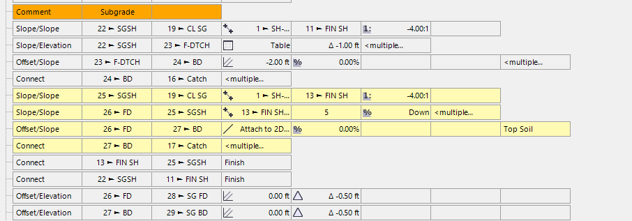
Your first check point is really at 12’ from the toe of slope (your Point 7) at 0% cross slope from the Toe of slope - if this point is below existing then your control is on the inside of the ditch to be 1’ to base of ditch, whereas if it is Above existing your control is on the outside of the ditch - from that point you can create a point on OG using side slope to OG with a slope of “Down” (vertically down) to tie to OG and from there you want to offset slope towards the CL using Delta Elevation of -1 and slope of 4:1
While this is not your project - the instruction set shows how the conditions work with a 6:1 outer slope and a 4:1 inner slope. If the ditch slopes are varied along the route then I would have to think how to handle that (for slope values you can use node to node to follow the slope of something existing earlier in the template instruction list) or you can use tables or some combination of the two - again I would have to look at the specific examples to work out what to do exactly - I hope that this example shows you how to compute this at least to some degree. I can try to find time to look at your specific use case in more detail - however the typical says -4:1 yet your template said -2:1 so they did not match and without the full plans and a chunk of time applied to this it is hard to show you exactly how to solve this.
Please raise a Support Ticket with Chris Bayliff at Support@RockpileSolutions.com and he can call you to help you more with this.
Note that I feel that this is just meeting the criteria of the ditch - however you will likely need to design a ditch profile grade line to make sure the water drains correctly and then use that Ditch PGL to define the model / design - we have videos on how to use a Ditch PGL to form a model for a ditch element - link is here - Click Here.
I solved this utilizing the ditch feature lines elevated to the OG surface. Slope/Sope from Face of Ditch to the intersection of the finish fore-slope. The rest falls into place. The back-slope is variable so the real issue was the maintained 4:1 for the fore-slope