Cloud Services - Label Alignment

Function Overview
The Label Alignment function creates labels for selected horizontal alignment that include the following elements
- POB Label (Station, Northing, Easting)
- Line Segment Labels (Segment Length, Segment Bearing)
- Spiral Segment Labels (Spiral Length)
- Arc Segment Labels (PI Station, PI Northing, PI Easting, Radius, Length, Chord Length, Delta Angle).
- POE Label (Station, Northing, Easting)
The labels are placed in relation to the alignment segments being labeled.
This command is designed to be utilized in association with the TBC Create Alignment Labels command, that will place the station markers, the interval ticks and the PC, PT, SC, ST, CS, SC etc. and Station Equation labels for the alignment.
Video Demonstration
The following video shows you how to use the command function
Release History
July 2025 - Version 1 released
Command Inputs
The Label Alignment command dialog looks as follows
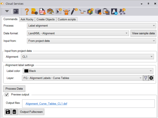
Process
Select the Label alignment process from the list of options
Data format
Select LandXML - Alignment - this is the format that is used to supply the alignment information to the cloud service command for it to generate the labels for the alignment.
Alignment label settings
Label color
Select the color that you wish to draw the labels in from the pull down list of colors.
Layer
Select the layer that you wish to draw the alignment labels on, pick from the pull down list or define a new layer / Layer group using the new layer control at the end of the layer selector.
Process Data button
When you have made your alignment selection, and set the settings as you want them, click he process data button to execute the creation of the alignment curve tables / segment labeling.
The labels are created as Multi line text objects, and are placed adjacent to the alignment segments being labeled.
The text height for the labels is currently hard coded in the command. You can change the text height of the labels after they have been created in TBC,
On completion of the process, the alignment labels are placed in the plan view graphics.
Data Outputs
A DXF File of the alignment labels called Alignment_Curve_Tables_Alignment Name.dxf is also created as a part of the process. The file is displayed in the output Files section of the dialog, Click the file name to open the folder location in which the file is stored.