CAD Cleanup Command

Latest Updates
Aug 30 2023 - Command Released
Command Licensing and Default Menu Location
- The CAD Cleanup command is part of the RPS Data Prep Toolbox
- The command is located on the Data Prep macros menu ribbon
- The command is located in the Cleanup menu group
Command Description
Provides a work process tool to cleanup and sort imported CAD files. The command includes a CAD Block processor to manage and explode imported blocks, a Layer control to manage and group imported layers based on predefined rulesets, and a set of miscellaneous controls to delete imported plan sets, delete AEC object references, zero length lines and empty unprotected layers, change text to multiline text and change text styles to stroke fonts for improved graphics speed.
Video Demonstration
The following video shows how to utilize the CAD Cleanup command
Command Interface Description
The CAD Cleanup command dialog looks as follows

There are three operational tabs designed to be executed in sequence order
Step 1 - Explode Blocks
Step 2 - Miscellaneous
Step 3 - Layers
Navigate items
When you import many CAD files, it is not uncommon for the file to have data objects at or around 0,0 coordinate and at or around the project coordinate area. When the file import is completed, TBC will zoom extents and in many cases you will not be able to see or even find the data area that you need. You cannot simply delete the data at 0,0 because that will often be the origin of blocks in the CAD file that contain many data objects required for the project.
Find Previous / Find Next
Use the Find Previous or Find Next buttons to step through the project data objects until you find an object that is in the middle of the project data area. Zoom out a little to review the entire project area and then use the Defined Views function (see below) (accessible from the Header Bar commands in the dialog) to capture a saved view of that view for later recall if needed.

Reload
If you import a new CAD file while running the command, click the Reload Button to refresh the Block List, Layer List and Miscellaneous Items for a second or subsequent execution of the cleanup process. The lists etc., are fresh each time you start the command.
Create and save Defined Views
We recommend that while running this command, you may want to also utilize the Defined Views function to save views that can be easily recalled. The Defined Views function can be executed from the Header Bar commands.
Step 1 - Explode Blocks

In this tab of the dialog you will be exploding CAD blocks into their component objects. Many CAD files have nested blocks and objects that can run several levels deep. Typically you would select all data and then Explode the blocks using the Explode command. Once the first level is exploded you would repeat the process to remove the second level blocks. You would repeat this process until all the blocks in the project have been exploded and none remain. This is a time consuming process and typically results in all blocks regardless of the type of block being exploded into its component parts. This in turn means that blocks that represent point objects like Road Signs, Trees, Fire Hydrants, Manholes, Inlets etc. no longer exist and can no longer be counted for takeoff purposes.
The Blocks function in CAD Cleanup changes that process dramatically through offering a Block Explorer capability - allowing you to clearly see the list of Blocks, those that have been used in the project and how many times, and how many objects each block contains. In addition by clicking on a block in the list, the block instances will be highlighted graphically allowing you to see them and determine how you may want to process them (Explode / Do Not Explode). You can press the Left and Right arrow keys on your keyboard to step through the Block Instances of the selected block if needed.
Typically blocks that have a single instance that contain other blocks and that contain a large number of objects were created in AutoCAD using e.g. the WBLOCK command that allows you to write out a selection of objects to a new DWG file. Blocks that contain a smaller number of objects and no embedded blocks and that have been used many times in the project, are typically blocks that represent features such as Road Signs, Manholes, Fire Hydrants etc.. and these are best left unexploded. The names of the blocks can help to identify what they represent.
The command reviews all of the blocks at the current “nest level” and analyzes the following information and tabulates it, sorting the blocks that you most likely want to explode (checked) from those that are less likely (unchecked). you can override those that are checked or unchecked in the list as you see fit.
In the Block list you will see the following information columns
Block Name - The name of the block
Items - the number of objects contained in each block instance of that name
Blocks - the number of embedded blocks nested within the block
Used - the number of instances of the block in the project at the current nest level. Note that if you use the Explode Selected approach to exploding Blocks, after each explode, the block list will change as more / different blocks are exposed from their source blocks at the next nest level down. If you use the Explode All approach to exploding blocks. all nest levels and all Blocks are exploded in a single step.
Blocks with a large number of items, that incorporate one or more blocks inside that have been used once are the blocks most likely to need exploding. These are identified and are selected automatically.
Blocks with a large number Used or not used at all and fewer items in each block that contain no embedded blocks are the least likely to need exploding.
Note:
In this process, the explode block process will also delete the hidden content of blocks that are assigned a visibility status in the AutoCAD DWG file. Visibility status blocks can have hidden content that is exposed when you change the visibility status of the block. TBC natively does not support the visibility status, however if you use the standard TBC explode command on blocks with this enabled, the hidden linework embedded in the blocks will be exposed. The CAD Cleanup command will delete the hidden content, leaving only the linework with the visibility status = On in the currently selected visibility status of the block. See the video lower down in this post for more details about blocks with visibility status.
Explode Selected
Check the check boxes next to those blocks that you wish to explode and then click Explode Selected to carry out selective exploding of Blocks. This will explode a single nest level only each time you make a selection and use Explode Selected.
Explode All
If you wish to move quickly and not preserve the small object type blocks, simply click Explode All to automatically explode all of the blocks in the project. This process will recursively explode each level of nesting in the imported / selected data until there are no blocks left to explode.
Delete exploded block definitions checkbox
If you wish to delete the block definitions of the exploded blocks, check this checkbox. Note that if you select Explode All, and have this checkbox enabled, all of your block definitions will be deleted. We recommend that you use this checkbox only when using the Explode Selected method.
Report Area
On completion of the process, the report area at the base of the dialog will display the changes that were made to the project based on each of the requested steps. If you wish to keep a record of the CAD Cleanup steps that were executed, you can copy and paste the information area content to the clipboard and then paste it into an external document (Word, Notepad, Excel etc.) or into the TBC drawing if required using the RPS Paste command.
When you have completed the Block Exploding process you are ready to move onto Step 2 - Miscellaneous.
Step 2 - Miscellaneous
In this step you will clean up a number of commonly occurring issues associated with imported CAD data. Select the items that you want to clean up and then click the Clean up miscellaneous items button to execute.

Object Selection
You can run these processes on all of the data in the project or just a selection of the data objects in the project. Select All Objects or Selection. If you select Selection, select the objects you want to process graphically or through use of the advanced selection methods available from the Options button (Select by Elevation, Select by Layer, Advanced Select etc.)
Delete AEC objects checkbox
CAD files created from Autodesk Civil 3D will often have “proxy objects” in the CAD drawing that reflect the presence of a Civil 3D AEC object (e.g. a Pipe, Manhole, Fitting, Surface, Alignment etc.) that are stored in the CAD file as an AEC object but are currently unreadable by anything other than Civil 3D itself.

In this situation the proxy objects are typically drawn as a rectangle on a layer with a line of text in the lower left corner that says AeccXXXXXXXXXXXXXX indicating the type of AEC object that is present at that location. The size of the box I believe is indicative of the geographic extents of that object in Civil 3D. These objects are useless in TBC, can be scattered across many layers and are hard / time consuming to clean up. Click this checkbox to find and remove these objects.
Delete zero length lines checkbox
As CAD engineers clean up or create drawings, they will often leave behind small (very short) line segments that have a zero length. These are what TBC calls zero length lines. Check this checkbox to remove zero length lines from your project
Set all text to use stroke fonts checkbox
CAD files will often use True Type fonts because they look nicer on plot sheets. True Type fonts are heavier to use in TBC than stroke fonts and will slow down the graphics regeneration, significantly in some situations. Use this option to temporarily convert all True Type text into Stroke Font text to improve your graphics performance. The text styles can be reset to True Type using the RPS Text Style Manager at any time.
Convert CAD Text to Multiline Text checkbox
CAD technicians placing single text items on drawings will often use CAD Text vs Multiline Text to create those objects. Multiline text objects are more flexible in TBC, so you can convert CAD Text to Multiline Text here as an option. Multiline text allows you to insert smart text controls and complex text formatting into the text.
Delete empty layers / Include protected layers checkboxes
Engineering companies use a CAD Template in the same way that you use project Templates in TBC. A CAD Template will typically have all of the layers that the Engineering company use by default. In the process of creating a CAD project, the engineer will use some but likely not all of the layers defined in their template. If they save the DWG file and provide that to you, it is likely that the DWG file will have many layers that do not contain any information (CAD objects). If you wish to remove unused empty layers select this checkbox.
In your TBC Project Template, that you use to start a new project, it is likely that you will have Layers and Layer Groups of your own that you use in your Data Prep, Modeling and Survey work. These layers should have layer protection set to On (use Layer Manager to do this). Protected Layers will not be removed if they are empty, unless you check the Include protected layers checkbox.
Make low elevations undefined / Tolerance checkboxes
DWG files will typically contain a variety of objects defined at a variety of elevations. In AutoCAD they don’t really have the concept of an undefined elevation as we do in TBC so they use Elevation 0 or a large negative elevation e.g. -999.999 etc. as undefined. These values of course can be real if you work at sea level or in a marine environment, but for many projects it is pretty evident that Elevation 0 or -999.999 etc. is not a real elevation. Different engineers may use alternative values to mean undefined. Even within the same project you may find a variety of elevations that represent undefined, so we also allow you to define an elevation below which the command will change all values to undefined.
In addition, you will also find lines that have true elevations but in some places they have elevation 0, resulting in spikes in any resulting surface models that use the lines. The command will shortly also address this issue as well.
Check the checkbox to set low elevations to undefined, and then specify the elevation below which you wish to set the objects to undefined e.g. 0.000 will catch 0.000 as well as -999.999, -9999.999 etc. and set those objects to undefined.
Remove block visibility states
If in the first step you were selective about which blocks to explode, you may have decided to retain some blocks that have the AutoCAD visibility status associated with them (see the video below). Blocks with visibility status have block elements that are currently visible and some block elements that are currently hidden from view (reserved for other visibility states of the block). For example a light pole could be a single, double, triple or quadruple head light pole. These could all be defined using different blocks in AutoCAD or they could be defined as a single block with different visibility states (Single, Double, Triple or Quadruple states). When the block is placed, the user can define which visibility state should be present at that instance of the block insertion. The data associated with the other states is hidden from view. When the block is then saved and imported into TBC, you will see the current visibility state only in the graphics, however the other lines / text etc., are present but hidden from view. This process step allows you to remove the objects that are hidden from view from the block definitions so that only the currently visible elements remain. That way, if you later decide to use the TBC Explode function to explode those blocks, you will only generate the linework that is present in the current visibility state. Without this cleanup process, exploding the blocks using the current TBC explode commend will generate all of the linework (visible and hidden) for all blocks that have this visibility state property. The Video below explains this in more detail.
Plan Sets
CAD Drawings have two main areas where you will find data. The Model Space (equivalent to the TBC Plan or 3D view) and Paper Space (equivalent to the TBC Sheet View).
In the TBC Sheet View you can display Plan Sets, Sheet Sets and Sheets for drawing creation purposes. The TBC Project Template that you used to create the project, may have Plan Sets, Sheet Sets and Sheets defined within it that you do not want to delete, however after importing CAD files you will nearly always find new Plan Sets, Sheet Sets and Sheets that were not a part of your template that increase the size of the project and are unnecessary for many Takeoff or Modeling processes.
You can select the Plan Sets, Sheet Sets and Sheets that you want to remove here, and if the CAD file also had View-Ports defined (equivalent to TBC Dynaviews) you can elect to delete those also. Note that if you have already been working in the project and have created drawing sheet output that resides in the Plan Set, Sheet Set, Sheets area of the project, be careful not to delete Dynaviews or Sheets Sets that you want to keep.
Clean up miscellaneous Items button.
Once you have set the settings as you want them, click this button to process the CAD data through the miscellaneous cleanup steps.
Report Area
On completion of the process, the report area at the base of the dialog will display the changes that were made to the project based on each of the requested steps. If you wish to keep a record of the CAD Cleanup steps that were executed, you can copy and paste the information area content to the clipboard and then paste it into an external document (Word, Notepad, Excel etc.) or into the TBC drawing if required using the RPS Paste command.
When you have completed the Miscellaneous Cleanup process you are ready to move onto Step 3 - Layers.
Step 3 - Layers

CAD systems like AutoCAD and MicroStation have Layers. Those Layers are recreated in TBC when you import a CAD file (DGN or DWG files). The Layers in those CAD systems can be named however the Project Engineering Company decides, however more and more we are seeing CAD files that adhere either tightly or loosely to the National CAD Standards.
In TBC we also have the concept of Layer Groups. A Layer Group allows you to put a number of layers together into a Layer Group that can then be turned On / Off as a Group, making it faster and easier to navigate large numbers of CAD Layers.
In TBC we also have the concept of Layer Categories that is used primarily in the TBC Takeoff application for construction estimating. While a Layer Category can be correlated to Layer Groups, there is no defined link between a Layer Group and a Layer Category. Categories are used to Group Layers as follows
Original - 3D data (points and lines primarily) in this category will be used to create the Original Ground Surface model for the Takeoff process. They will also define the lines that represent areas to be demolished and a line that defines the Original Ground surface model boundary.
Design - 3D data (points and lines primarily) in this category will be used to create the Finished Design Surface model for the Takeoff process. They will also define the lines that represent areas in which Site Improvements will be assigned to create subgrade adjustments and a line that will be used to create the boundary for the Finished Design Surface.
Other - Other layers of information that are not related to Original, Design or Utilities categories. Layers of data in this category are typically used in takeoff for the determination of Area, Length and Count quantities.
Utilities - Layers that contain Design information for Storm, Sanitary, Water, Gas, Electric, Cable, TV and Telecom utilities.
Unused - Layers that contain information that will be unused in the Takeoff process e.g. Annotation, Labels, Drawing Sheet layers etc.
Undefined - Layers that have not yet been categorized into any of the above categories.
The Layers process step, provides the ability to create Rulesets that allow imported CAD layers to be Grouped into useful Layer Groups, and at the same time be Categorized for Takeoff. For example, the National CAD Standard defines the following structure for layer names.
The Layer Names will have the format AA-BBBB-CCCC-DDDD-E where
AA is reserved for the Discipline Code
BBBB is reserved for the Major Group Code
CCCC is reserved for the Minor Group Code
DDDD is reserved for a second Minor Group Code
E is reserved for the Status Code
The Discipline Code can be one or two characters, the first character is the master Discipline Code and can be one of the following
A = Architecture
B = Geotechnical
C = Civil (Design)
D = Process
E = Electrical
F = Fire Protection
G = General
H = Hazardous Materials
I = Interior
L = Landscape
M = Mechanical
P = Plumbing
Q = Equipment
R - Resources
S = Structural
T = Telecommunications
V = Survey and Mapping
W = Distributed Energy
X = Other
Z = Contractor Shop Drawings
So it is logical for Layer Groupings to follow this convention as a fast and easy way to sort out imported CAD files.
Secondly the Major Codes can be a second division of the Groups i.e. the Civil Group can have Major Codes including the following examples
ROAD = Road
SSWR = Sanitary Sewer
STRM = Storm Sewer
WATR = Water
TELE = Telecom
CATV = Cable TV
and these can be used to further subdivide the imported Layers into Layer Groups for example any layer name including SSWR, STRM, WATR etc. could all be placed in a C - CIVIL - UTILITIES Layer Group or they could be further Subdivided into their individual types of Utility e.g., C-CIVIL-UTILITY-WATER or C-CIVIL-UTILITY-STORM SEWER etc.
In addition, for layers that will contribute to the Original Ground surface model or the Finished Design surface model, you will likely want to separate off layers that contain Text Labels, Dimensions, Annotation Text etc. so that those labels do not get used to create 3D points in the surface models. In this case, any layers that contain key characters like TEXT, LABL, ANNO, DIMN etc. should be separated into e.g. C-CIVIL-ANNOTATION or C-CIVIL-UTILITY-ANNOTATION Layer Groups.
So based on the above scenario, if you are receiving CAD files, that to a large extent are utilizing the National CAD Standards, you can define a RuleSet that processes the Layers into Layer Groups according to what you think you require. Those RuleSets can be saved, copied and edited if you find additional splits that you require, or if you get variations in Layer naming that you want to account for.
In addition, as you define the rule that moves Layers with certain naming conventions into your defined Layer Groups, you can also Categorize those layers into the Takeoff Categories, so that your separated data is also ready for Takeoff modeling as it is later made into clean 3D linework etc.
Rulesets
A RuleSet can be defined within the command itself or from within the RPS Settings command accessible from the Header Bar or the Tool Shed menu.

A Ruleset comprises a number of rules. The rules are processed sequentially, so the order in which the rules are defined has an effect on the outcome. For example if the Ruleset includes the following sequence

The second rule will never be applied because both rules use C or C- as the first characters of the rule search and the first one will win.
If the sequence is reversed

Then the Layer C-STRM-PIPE will go to Layer Group C - CIVIL - UTILITIES
Any other Layer starting with C- will go to Layer Group C - CIVIL
If we then modify the Ruleset and add a third line as shown below
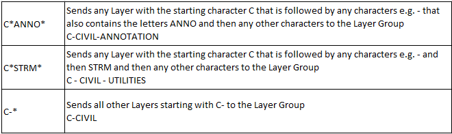
- This will first separate out all layers in the Civil discipline (C-) that contain the characters ANNO into the C-CIVIL-ANNOTATION Layer Group.
- Second it will separate out all of the Storm Sewer Layers excluding any that have the characters ANNO in the name and place them in the C-CIVIL-UTILITIES Layer Group
- Lastly it will separate out the remaining Civil discipline layers and place them in the C-CIVIL Layer Group.
Through this Ruleset definition, you can create a set of rules that can be applied to any CAD file to separate out the layers into logical groups if they follow the National Cad Standard guidelines.
If the CAD file is not using the National CAD standard guidelines, you can still create a Ruleset just for files from that Engineering firm, that once defined will apply to any CAD file that they generate using their own internal standards.
The above examples are all using a simple rule definition where the * character is used as a wild card allowing any number of any combination of characters fills the gaps between defined character sequences like C- or ANNO or STRM or SSWR etc.
If you have complex instructions that you wish to create, you can use full Regular Expression functionality. We do not attempt to train you in this help document how to define Regular Expressions, we are happy to help you and also provide a few examples below that may assist you to construct your first complex rules.
A Ruleset needs to be defined using all Simple Instructions or all Regular Expressions. Each Ruleset has a setting for regular Expressions which when enabled, will process only rules that use regular Expressions.
A Ruleset can be tagged as being Case Sensitive or not. If you specify it as being Case Sensitive, defining ANNO in the Rule will look for upper case characters only i.e. anno or Anno or AnNo would not be found, only ANNO will work. If you define the Rule Set as non Case Sensitive then ANNO will find Anno, AnNo, anno as well as ANNO in Layer Names.
Note that NCS recommends all upper case letters for Layer Names.
Creating or editing a Ruleset
- Select the Ruleset that you wish to Edit from the Ruleset selector in the command.
- If you wish to create a new Ruleset, run RPS Settings from the Header Bar commands and use the Ruleset Editor in the CAD Cleanup section of RPS Settings.
- In RPS Settings, you can copy an Existing Ruleset to create a new Ruleset definition using the Copy button.
- In RPS Settings, you can edit the name of a Ruleset using the Edit button
- In RPS Settings you can provide a Description for a Ruleset
- In RPS Settings you can Save changes to a Ruleset using the Save button
- When you define a Ruleset select if the Ruleset will be Case Sensitive or not.
- When you define a Ruleset select if the Ruleset will use Regular Expressions or not.

RPS Settings Ruleset Editor
Creating or Editing a Rule within a Ruleset
- Select the Ruleset that you want to work with from the Ruleset selector.
- You can add or edit rules to the selected Ruleset from within the CAD Cleanup Command or from the RPS Settings - CAD Cleanup function.
- Click the
 button to add a rule to an existing Ruleset.
 - Select a Rule in the list of rules, and click the Copy button to copy an existing rule to create a new or modified rule in the Ruleset.
- Select a Rule in the list of rules, and click the Delete button to delete an existing rule in the ruleset.
- To insert a new Rule below an existing rule, select the rule in the list below which you want to add the new rule. Click the Add rule button. The new rule will be inserted below the currently selected rule.
Tip
Create your rules in logical groups so that the Ruleset is easy to interpret i.e. cluster all your rules for C- layers and V-layers together etc.
Rule Definition
A rule in a Ruleset has the following controls
- Active checkbox - enable the checkbox to activate the rule in the Ruleset. When inactive the Rule will not be used in the processing of Layers into Layer Groups.
- Search - this defines the character search to be applied by this rule e.g. C-ANNO
- Group - this defines the name of the Layer Group that will be created / applied to the Layers that match the Search criteria. All layers that match the Search criteria will be placed in this Layer Group.
- Visibility - this allows you to set the visibility status of the Grouped Layers after processing. The options are No Change, Hidden or Visible. This allows you to hide layers that you are less interested in during this process.
- Takeoff Category - select the Takeoff Category that you want to use for the Layers that meet the Search criteria defined by the Rule e.g. C- layers could become part of the Design category, V- layers could become part of the Original Category and C-STRM or C-SSWR or C-WATR could become part of the Utilities Category. Layers that contain CANNO or CLABL or CTEXT or CDIMN could become part of the Unused Category etc.
Remember that the rule order in the list is important. If you get a Rule in the wrong place, you can move it up and down the list using the Up and Down arrow buttons at the base of the list.
In the Top section of the Layers tab, you will find your project Layer list. As you define rules, you will see which layers the rule is affecting - the Takeoff Category and the Layer Group will update based on the rule definition allowing you to preview the results prior to committing the Process Layers button.,
Notes:
You can process the Layers with one Ruleset, you can then modify or change the Ruleset and process the Layers again to see the differences between Rulesets, however once a layer Group has been created, unless you use the Undo command to Undo the processing, the Layer Groups that are created on each process will persist unless deleted using the Layer Group Manager command.
When you have processed the layers, take a look at your View Filter Manager and turn off all the Layer Groups and then review each Layer Group to see the results. If you find any issues with the way the data is structured, try modifying your Ruleset and reprocess the data until you get the desired results.
If you cannot work out the rules that you need, please contact us for assistance - we will do what we can to help you define the rules using Simple or Regular Expressions to provide you with a solution.
Example RPS Settings File for the CAD Cleanup Command
Below you will find a started CAD CLEANUP.RPS settings file that contains a number of examples linked to the National CAD Standards that will help you to get started. Place this file in your RPS Settings folder.
CadCleanupRules.rps (29.2 KB)
In this example you will find several Rulesets, some use the simple search criteria and the others utilize Regular Expressions to give you some working examples to use as a basis of your own Rulesets.
Close
Closes the command without further execution.
US National CAD Standards (NCS)
More and more government agencies, DOTs and Engineering Firms are adopting the US CAD Standards for CAD drawing operations. One of the guidelines laid out in the standards is that of Layer Naming conventions. You can find the full documentation for the Layer Naming standards at this link
Simple Rules and Regular Expression Based Rules
The CAD Cleanup Layer Grouping control, provides the ability to sort a list of imported CAD layers into Layer Groups based on the names of the layers being processed. The rules can be defined using either simple instructions (simple rules) or regular expression instructions (advanced / complex rules).
Simple Ruleset Filter Instructions
The following examples will assist you to build simple rulesets for organizing layers into layer groups based on the layer naming conventions. If the engineers are using NCS standard layer names, it is a relatively simple task to create a ruleset that sorts the layers into the main Discipline Groupings of the NCS standard (A-* = Architecture, C-* = Civil, V-* = Survey & Mapping etc.)
Simple rules typically use only a combination of real characters and the * or ? to represent wild card sequences of characters. The * represents any number of characters of any character anywhere in the layer name after any preceding characters i.e. C-* means find specifically layers starting with C- followed by any character sequence. The ? represents any single character in the position directly after the specified characters so C-? means any 3 characters where C- are the first two and the third character c an be any character.
You can also define a series of searches, separated by a pair of colons e.g. A-::B-::C-* will search for any character sequences starting with A- or B- or C- etc. Note do not place a pair of colons after the last string.
Example Simple Search Expression Rules

Regular Expression Examples
Regular Expressions provide an industry standard way of defining complex rules for processing data - in this case defining rules that organize imported CAD layers into TBC layer groups quickly based on the names of the layers being processed.
We are not expecting all of our users to become programmers, the Simple Expressions approach will solve a large number of common Layer Naming standards, however sooner or later you are going to find a situation that cannot be solved with a simple expression and you are going to need more. When you want to use regular Expressions, share the file with us that you are trying to process, and draw up a Layer to Layer Group map of what you want to achieve and we can create you an RPS Settings file for a consulting fee if required that will work. We will post more and more examples of Regular Expressions that help process different scenarios over time, so that you will have a reference to look at when needed.
There are many On Line resources for Regular Expressions - below you will find a couple that we find helpful. Regular Expressions are extremely powerful in use but a little tricky to learn how the rules are constructed.
Regular Expressions Reference Documentation Link
Click Here
On line Regular Expressions Testing Tool
Click Here
The Excel Spreadsheet below provides a worked example of a CAD Layer List and a set of Regular Expressions that can be used to separate out the Layers into the defined Layer Groups and Layer Categories.
Regular Expressions Example.xlsx (14.4 KB)
Here is the source CAD file that generated this Layer List if you want to test it out
Base File ACAD-1211 A-SITE.dwg (3.6 MB)
Use Case Videos
The following videos show the use of the CAD Cleanup command in a work process context
Feedback and Enhancement Requests
If you would like to provide feedback on the use of the CAD Cleanup command or to request enhancements or improvements to the command please Click Reply below