Add Isopach

Command Licensing and Default Menu Location
- The Add Isopach command is part of the RPS Modeling Toolbox
- The command is located on the Modeling Toolbox menu ribbon
- The command is located in the Surface menu group
Command Description
Provides the ability to add back or subtract a percentage of the difference in volume between two surfaces in order to surcharge a surface to allow for settlement or to remove additional material as a percentage of cut depth to allow for over excavation for example.
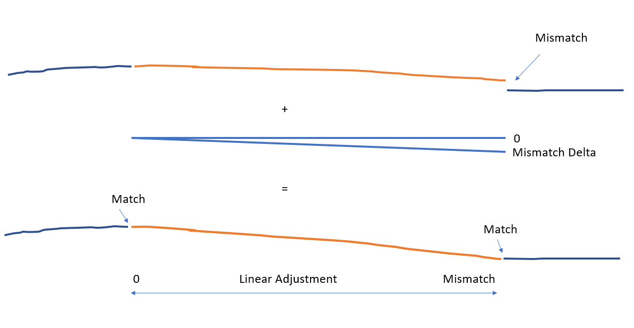
You can also now use the command to adjust a surface using an “adjustment surface” as the isopach i.e. if you have a road model that is correct at some point before you get to a bridge deck, but at the bridge deck you are off by say 0.15’ then you can create an adjustment surface that has a 0 elevation at the point where you want to start a transition to taper the surface model to match, and have the adjustment surface have an elevation of -0.15 at the bridge deck location. This will cause the road model to adjust gradually from the 0 point to the 0.15 adjustment at the bridge deck.
Command Training Video
The following video shows how to utilize the Add Isopach command
Update Information
May 2023:
Further improved the command dialog and functionality to allow surface adjustments to be made over an area defined by the isopach to facilitate matching grade at project limits or matching grade of e.g. approach and departure roads to bridge decks etc. The command now supports an Isopach surface that covers an area larger or smaller than the reference surface and that only partially overlaps the reference surface. We also added the ability to add an offset line to the isopach adjustment area so that the adjustment area ties back to the reference surface creating a vertical step around the adjustment area. Additional Header Bar commands were added to make this a Work Process Tool.
Dec 2022:
Improved the command dialog layout to bring it into line with RPS Standards and for workflow understanding and productivity.
Command Interface Description
The Add Isopach Command dialog looks as follows

Pre-requisite Process
In order to run this command, you will need a reference surface (the surface that you are going to adjust) and an Isopach / adjustment surface (the surface that you are going to use to adjust the reference surface).
The Isopach surface can be a difference / cut fill surface determined between two surfaces e.g. if you want to simulate e.g. the earthworks situation when 20% of the Cut / Fill has been completed to determine interim volumes and an interim surface model

The Isopach Surface can be an adjustment surface that applies constant height adjustments over the area of the isopach surface e.g. an Isopach Surface that has elevation -1 can be used to apply a height adjustment of -1 to the area of the isopach on the reference surface e.g. to apply subgrade adjustments or topsoil stripping to a reference surface.

The Isopach Surface can also be a variable height adjustment surface that applies variable height adjustments over the area of the isopach surface e.g. if you have a road that matches grade where it joins an existing road or a bridge deck - but your model mismatches at the join line, you can define a polygonal area (e.g. a rectangle) that has 0 elevations at one end and the height mismatch at the other end so that when applied to the reference surface, there will be a linear adjustment to the reference surface
Isopach Surface:
Select the Isopach surface that you want to use for the computation. The Isopach surface can be a true Isopach or just a surface drawn near the 0 datum that provides the information for the adjustment.
Include offset isopach boundary checkbox:
When you apply a polygonal area isopach surface to the reference surface, if there is a grade mis match around the perimeter of the isopach surface. it will retriangulate between the adjustment area and the reference surface to compute the resulting surface (when the reference vertices outside the isopach are included in the result surface. If you want to tie the adjustment area back to the reference surface with a near vertical step then check this checkbox to create a line at a 0.01 offset to the isopach boundary that is draped on the reference surface model and added to the result surface that is created.

Reference Surface:
Select the Reference surface that you want to use for the computation. The percentage of the Isopach that you select below will be computed and used to adjust the elevations of the Reference Surface to compute the new surface model.
Include reference nodes in new surface checkbox:
When checked, all of the 3D nodes of the reference surface that are within the bounds of the isopach surface will be adjusted by the isopach and included in the new surface that gets created (this will be the most common use case). When unchecked, only the nodes of the isopach surface will be computed and included in the new surface that gets created.
Include reference nodes outside isopach checkbox:
When checked, the nodes of the reference surface that lie outside the limits of the isopach will be left unadjusted and will be included in the surface that gets generated. When unchecked the new surface that gets generated will be limited to the area covered by the isopach surface only. When you select this method, you will likely also want to check the checkbox for the include offset isopach boundary.
New surface name:
Input the name of the surface to be created using the Reference and Isopach models
Cut factor:
For areas of the Isopach that have negative numbers (Cut) enter a factor / percentage of the Isopach model depth that you want to subtract from the reference surface e.g. 0.0 if you do not want to apply any factor or 0.1 if you want to apply 10%. To apply the full isopach surface adjustment enter 1.0
Fill factor:
For areas of the Isopach that have positive numbers (Fill) enter a factor / percentage of the Isopach model height that you want to add to the reference surface e.g. 0.2. To apply the full isopach surface adjustment enter 1.0
Note:
If your Isopach was computed between Existing Ground and Finished Design and you want to use this command to simulate the volumes moved over time (progress quantities) by adding back some of the Isopach volume to the Design Surface, then enter the factors as negative values. If you are adding back some of the Isopach volume to the Existing Surface then enter the factors as positive values to get the desired results.
Note when you are applying a factor to the Existing Surface e.g. Cut 0.2, Fill 0.2 this will adjust the reference surface by 20% of the Cut and by 20% of the Fill. When you are applying a factor to the Design Surface then you are going to enter a factor that is the % of the total Fill or total cut i.e. 80% of the Cut and Fill against the Design is the equivalent of 20% of the Cut and Fill against the Existing surface.
Command Tips
The command tips area can be minimized or opened using the orange arrow in the top left corner. The command tips provide helpful tips on how to run the command and also any shortcuts or hotkeys that may have been implements into the command.
Header Bar Commands
In the header bar of the command dialog, you will find commands that we believe may be used while running this command to provide you with quick access to those commands while running the Add Isopach command. The commands include the following
- Help
- RPS Settings
- Takeoff Lines
- Smart Edit
- Adjust Linestring Elevation
- Edit Linestring
- Offset Line
- Adjust Linestring Elevation
- Change Elevation
- Create Surface
- Add / Remove Surface Members
- Add / Remove Surface Boundaries
- Trim Surface Edge
- Surface Slicer View
- Earthwork Report
Apply:
Executes the command and readies itself for a second execution.
OK
Executes the command and closes on completion
Cancel
Closes the command without further execution.
Use Case Videos
The following videos show the use of the Add Isopach command in a work process context
In the following video we show how to use the Add Isopach command to adjust road elevations from a corridor model to match the elevations at a bridge deck over a length of the road on the approach / departure to the bridge. You can use this same approach to adjust the earthworks for a surcharge depth in the same way.
Feedback and Enhancement Requests
If you would like to provide feedback on the use of the Add Isopach command or to request enhancements or improvements to the command please Click Reply below.